- HOME
- 產品介紹
- 半導體事業部
- Hamamatsu Photonics
- Image Intensifiers (I.I.)
- Image Intensifier
Image Intensifier
![]() +886-2-8772-8910
+886-2-8772-8910
Image Intensifier
Image intensifiers (often abbreviated as I. I.) were primarily developed for nighttime viewing and surveillance under moonlight or starlight. Image intensifiers are capable of detecting and amplifying low-light-level images (weak emissions or reflected light) for bringing them into view as sharp contrast images. Image intensifier applications have spread from nighttime viewing to various fields including industrial product inspection and scientific research, especially when used with CCD cameras (intensified CCD or ICCD). Gate operation models are also useful for observation and motion analysis of high-speed phenomena (high-speed moving objects, fluorescence lifetime, bioluminescence and chemiluminescence images). Some major image intensifier applications are introduced here.
APPLICATION EXAMPLE
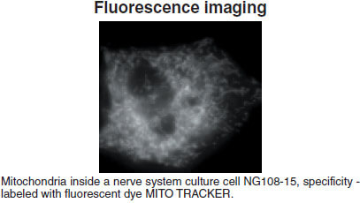
Fluorescence imaging
Fluorescence imaging
Fluorescence imaging
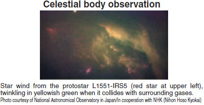
●Low-light-level imaging ●Multi-channel spectroscopy ●High-speed motion analysis ●Bioluminescence or chemiluminescence imaging ●UV range imaging (Corona discharge observation)
FEATURES
Feature 1:WIDE VARIATIONS
A wide variety of characteristics is presented including spectral response by choosing a photocathode and window material combination, photocathode size, the number of MCPs (gain) and gate time. You are sure to find the device that best matches your application from our complete lineup of standard or custom products.
Feature 2:HIGH RESOLUTION
Clear, sharp images can be obtained with no chicken wire.
Feature 3:COMPACT AND LIGHTWEIGHT
Proximity-focused configuration is more compact and lightweight than inverter type.
Feature 4:NO DISTORTION
Images without distortion can be obtained even at periphery.
Feature 5:HIGH-SPEED GATE OPERATION
High-speed gated image intensifiers are available for imaging and motion analysis of high-speed phenomena.
Feature 6:HIGH SENSITIVITY GaAs AND GaAsP PHOTOCATHODE
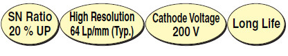
Excellent image intensification with an even higher signal-to-noise ratio is achieved by combining our filmless MCP fabrication technology with the high-sensitivity GaAs and GaAsP photocathode.
STRUCTURE
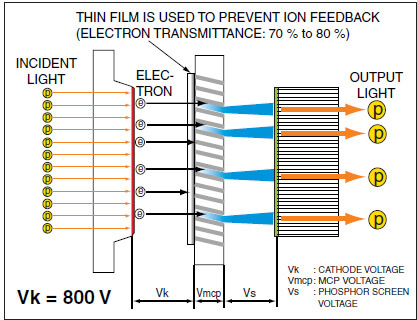
In conventional image intensifiers having a crystalline photocathode, a thin film was deposited over the surface of the MCP (microchannel plate) to prevent ion feedback. Our improved fabrication method successfully eliminates this thin film. This filmless structure eliminates the loss of electrons passing through the MCP and therefore improves the signal-to-noise ratio more than 20% compared to filmed image intensifiers, and the life is longer.
●Filmless MCP Type
●Filmed MCP Type
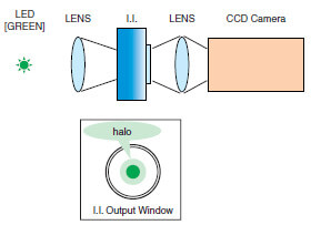
Low "halo" effect
Minimizes the halo effect that makes annular light appear around bright spots.
●Filmless MCP Type
●Filmed MCP Type
●System Configuration
STRUCTURE AND OPERATION
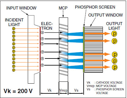
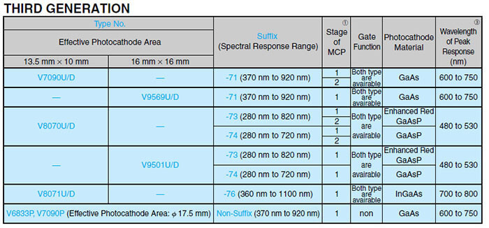
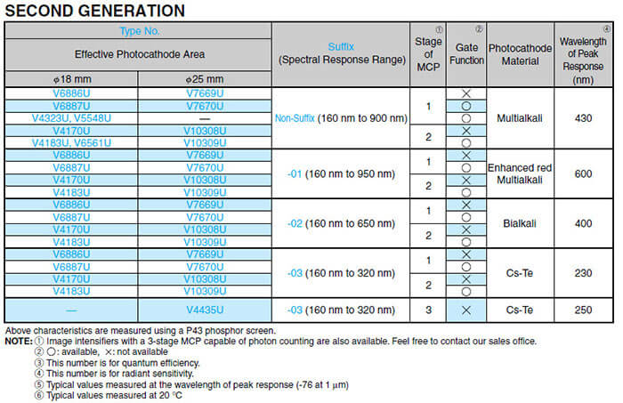
Figure 1 shows the structure of a typical image intensifier. A photocathode that converts light into photoelectrons, a microchannel plate (MCP) that multiplies electrons, and a phosphor screen that reconverts electrons into light are arranged in close proximity in an evacuated ceramic case. The close proximity design from the photocathode to the phosphor screen delivers an image with no geometric distortion even at the periphery. Types of image intensifiers are often broadly classified by "generation". The first generation refers to image intensifiers that do not use an MCP and where the gain is usually no greater than 100 times. The second generation image intensifiers use MCPs for electron multiplication. Types using a single-stage MCP have a gain of about 10000, while types using a 3-stage MCP offer a much higher gain of more than 10 million. A variety of photocathodes materials are currently in use. Of these, photocathodes made of semiconductor crystals such as GaAs and GsAsP are called "third generation". These photocathodes offer extremely high sensitivity. Among the first and second generation image intensifiers,there are still some inverter types in which an image is internally inverted by the electron lens, but these are rarely used now because of geometric distortion.
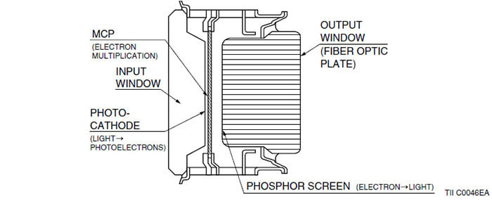
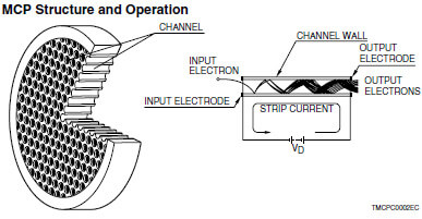
Figure 2 shows how light focused on the photocathode is converted into photoelectrons. The number of photoelectrons emitted at this point is proportional to the input light intensity. These electrons are then accelerated by a voltage applied between the photocathode and the MCP input surface (MCP-in) and enter individual channels of the MCP. Since each channel of the MCP serves as an independent electron multiplier, the input electrons impinging on the channel wall produce secondary electrons. This process is repeated several tens times by the potential gradient across the both ends of the MCP and a large number of electrons are in this way released from the output end of the MCP. The electrons multiplied by the MCP are further accelerated by the voltage between the MCP output surface (MCP-out) and the phosphor screen, and strike the photocathode which emits light according to the amount of electrons. Through this process, an input optical image is intensified about 10 000 times (in the case of a one-stage MCP) and appears as the output image on the phosphor screen.

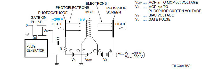
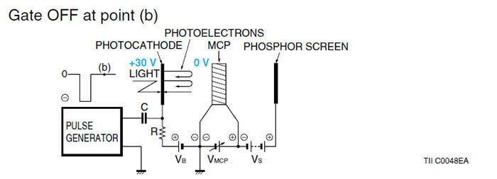
An image intensifier can be gated to open or close the optical shutter by varying the potential between the photocathode and the MCP-in. Figure 3 shows typical gate operation circuits. When the gate is ON, the photocathode potential is lower than the MCP- in potential so the electrons emitted from the photocathode are attracted by this potential difference towards the MCP and multiplied there. An intensified image can then be obtained on the phosphor screen. When the gate is OFF however, the photocathode has a higher potential than the MCP-in (reverse-biased) so the electrons emitted from the photocathode are forced to return to the photocathode by this reverse- biased potential and do not reach the MCP. In the gate OFF mode, no output image appears on the phosphor screen even if light is incident on the photocathode. To actually turn on the gate operation, a high-speed, negative polarity pulse of about 200 volts is applied to the photocathode while the MCP-in potential is fixed. The width (time) of this pulse will be the gate time. The gate function is very effective when analyzing high-speed optical phenomenon. Gated image intensifiers and ICCDs (intensified CCDs) having this gate function are capable of capturing instantaneous images of high-speed optical phenomenon while excluding extraneous signals. Figure 3: Gate Operation Circuits Gate ON at point (a)
EM-CCD cameras and image intensifiers using a one-stage MCP have been used in low-light-level imaging. However, these imaging devices cannot capture a clear image when the light level is lower than 10-5 lx. At such extremely low light levels, detecting light as an analog quantity is difficult due to limitations by the laws of physics, but detecting light by counting photons is more effective. Image intensifiers using a 3-stage MCP are ideal for photon counting. Image intensifiers with a 3-stage MCP can be considered high-sensitivity image intensifiers. However, these have two operation modes, one of which is completely different from normal image intensifier operation. At light levels down to about 10-4 lx, these 3-stage MCP image intensifiers operate in the same way as normal image intensifiers by applying a low voltage to the MCP. A continuous output image can be obtained with a gray scale or gradation. This operation mode allows the 3-stage MCP to provide a lower gain of 102 to 104 and is called "analog mode".
On the other hand, when the light intensity becomes so low (below 10-5 lx) that the incident photons are separated in time and space, the photocathode emits very few photoelectrons and only one or no photoelectrons enter each channel of the MCP. Capturing a continuous image with a gradation is then no longer possible. In such cases, by applying about 2.4 kV to the 3-stage MCP to increase the gain to about 106, light spots (single photon spots) with approximately a 60  diameter corresponding to individual photoelectrons will appear on the output phosphor screen. The gradations of the output image are not expressed as a difference in brightness but rather as differences in the time and spatial density distribution of the light spots. Even at extremely low light levels when only a few light spots appear per second on the output phosphor screen, an image can be obtained by detecting each spot and its position, and integrating them into an image storage unit such as a still camera and video frame memory. The brightness distribution of this image is configured by the difference in the number of photons at each position. This operation is known as photon counting mode.
Since image intensifiers using a 3-stage MCP can operate in both analog mode and photon counting mode, they can be utilized in a wide spectrum of applications from extremely low light levels to light levels having motion images.
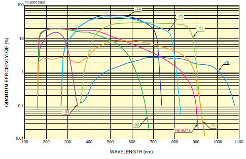
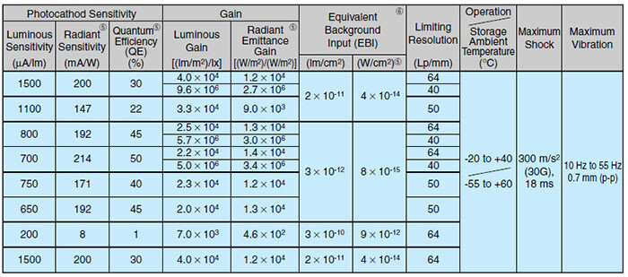
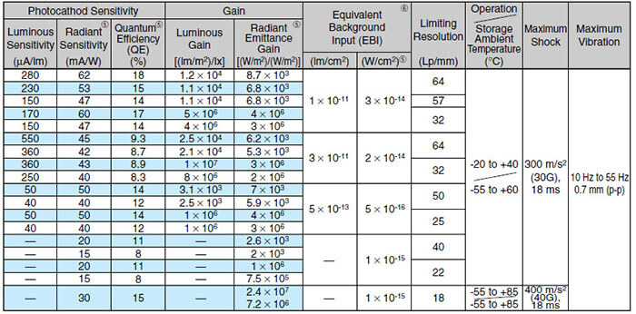
Photocathode Sensitivity
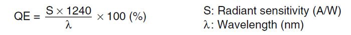
Luminous Sensitivity: The output current from the photocathode per the input luminous flux from a standard tungsten lamp (color temperature: 2856 K), usually expressed in  A/lm (microamperes per lumen). Luminous sensitivity is a term originally for sensors in the visible region and is used in this catalog as a guideline for sensitivity. Radiant Sensitivity: The output current from the photocathode per the input radiant power at a given wavelength, usually expressed in A/W (amperes per watt). Quantum Efficiency (QE): The number of photoelectrons emitted from the photocathode divided by the number of input photons, generally expressed in % (percentage). The quantum efficiency and radiant sensitivity have the following relation at a given wavelength
  .
.
Luminous Emittance
This is the luminous flux density emitted from a phosphor screen and is usually expressed in lm/m2 (lumens per square meter). The luminous emittance from a completely diffused surface emitting an equal luminance in every direction is equivalent to the luminance (cd/m2) multiplied by  .
.
Gain
Gain is designated by different terms according to the photocathode spectral response range. Luminous emittance gain is used for image intensifiers having sensitivity in the visible region. Radiant emittance spectral response range. Luminous emittance gain is used for image intensifiers having sensitivity in the visible region. Radiant emittance.
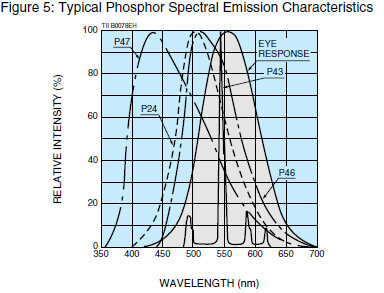
Photon gain is also used to evaluate image intensifiers using a P-47 phosphor (see Figure 5) whose emission spectrum is shifted from the relative visual sensitivity.
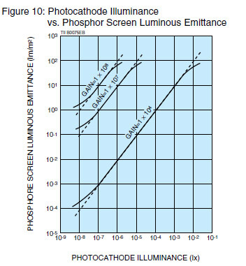
Luminous Gain: The ratio of the phosphor screen luminous emittance (lm/m2) to the illuminance (lx) incident on the photocathode. Radiant Emittance Gain: The ratio of the phosphor screen radiant emittance density (W/m2) to the radiant flux density (W/m2) incident on the photocathode. In this catalog, the radiant emittance gain is calculated using the radiant flux density at the wavelength of maximum photocathode sensitivity and the radiant emittance density at the peak emission wavelength (545 nm) of a P-43 phosphor screen.
Photon Gain: The ratio of the number of input photons per square meter at a given wavelength to the number of photons per square meter emitted from the phosphor screen.
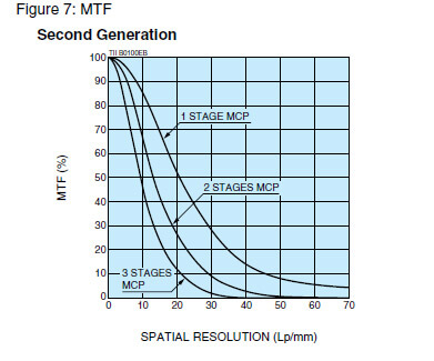
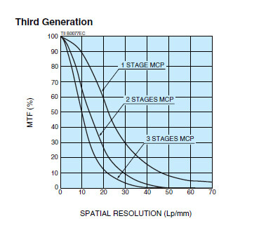
MTF (Modulation Transfer Function)
When a black-and-white stripe pattern producing sine-wave changes in brightness is focused on the photocathode, the contrast on the output phosphor screen drops gradually as the stripe pattern density is increased. The relationship between this contrast and the stripe density (number of line-pairs per millimeter) is referred to as the MTF.
Limiting Resolution
The limiting resolution shows the ability to delineate image detail. This is expressed as the maximum number of line-pairs per millimeter on the photocathode (1 line-pair = a pair of black and white lines) that can be discerned when a black-and-white stripe pattern is focused on the photocathode. In this catalog, the value at 5 % MTF is listed as the limiting resolution.
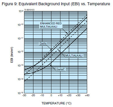
EBI (Equivalent Background Input)
This indicates the input illuminance required to produce a luminous emittance from the phosphor screen, equal to that obtained when the input illuminance on the photocathode is zero. This indicates the inherent background level or lower limit of detectable illuminance of an image intensifier.
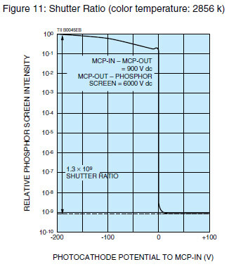
Shutter Ratio
The ratio of the brightness on the phosphor screen during gate ON to that during gate OFF, measured when a gated image intensifier is operated under standard conditions.
Dark Count
This indicates the noise level of an image intensifier using a 3-stage MCP when operated in the photon counting mode. The dark count is usually expressed as the number of bright spots per square centimeter on the photocathode measured for a period of one second (S-1/cm2). Cooling the photocathode is very effective in reducing the dark count. Usually, photocathodes (such as red-enhanced or extended red multialkali, GaAs and Ag-O-Cs) that tend to produce a large number of dark count at room temperatures should be cooled when used in the photon counting mode.
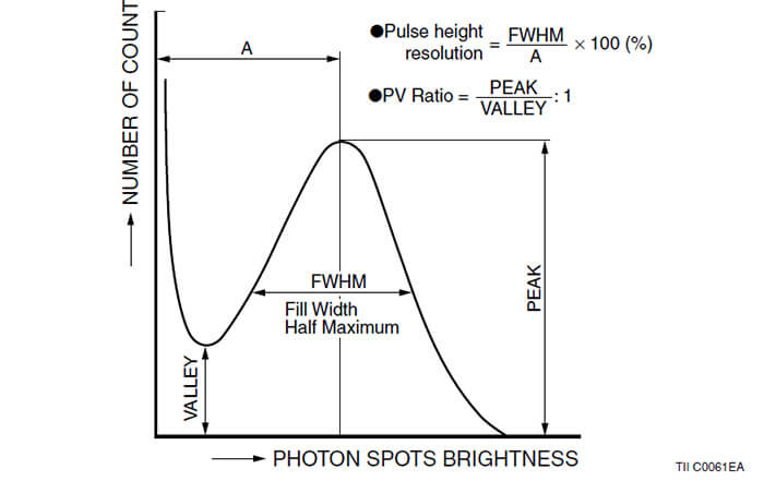
Pulse Height Distribution (PHD) on Phosphor Screen
Bright spots appear on the output phosphor screen when an image intensifier using a 3-stage MCP is operated in the photon counting mode. The pulse height distribution is a graph showing how many times a bright spot occurs on the phosphor screen, plotted as a function of brightness level (pulse height).
When an image intensifier is used with the MCP gain saturated, the brightness of each spot corresponding to each photoelectron is equalized on the phosphor screen to allow photon counting imaging. As noted in the graph below, the pulse height resolution and the P/V (peak-to-valley) ratio are used to indicate how the bright spots are aligned.
Gate Operation
Most photocathodes have a high electrical resistance (surface resistance) and are not suited for gate operation when used separately. To allow gate operation at a photocathode, a low-resistance photocathode electrode (metallic thin film) is usually deposited between the photocathode and the incident window. Gate operation can be performed by applying a high-speed voltage pulse to the low- resistance photocathode electrode. Metallic thick films or mesh type electrodes are provided rather than metallic thin films since they offer an even lower surface resistance. The gate operation time is determined by the type of photocathode electrode.
Since the semiconductor crystals of the GaAs and GaAsP photocathodes themselves have low resistance, no photocathode electrode film needs to be deposited for gate operation.
SELECTION CRITERIA (Factors for making the best choice)
A: at crystal photocathode
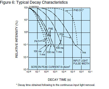
B: Depends on the input pulse width. Refe to Figuer 6 on page 6.
C: Relative value with output from P43 set as 1. Measured with 6 kV voltage applied.
D: Shutter time: Defined as the rise time. The input gate pulse width should be at least twice the shutter time.
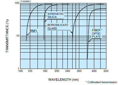
Figure 4: Typical Transmittance of Window Materials
A photocathode converts light into electrons. This conversion efficiency depends on the wavelength of light. The relationship between this conversion efficiency (photocathode radiant sensitivity or quantum efficiency) and wavelength is called the spectral response characteristic. (See spectral response characteristics on page 1.)
An MCP is a secondary electron multiplier consisting of an array of millions of very thin glass channels (glass pipes) bundled in parallel and sliced in the form of a disk. Each channel works as an independent electron multiplier. When an electron enters a channel and hits the inner wall, secondary electrons are produced. These secondary electrons are then accelerated by the voltage (VMCP) applied across the both ends of the MCP along their parabolic trajectories to strike the opposite wall where additional secondary electrons are released. This process is repeated many times along the channel wall and as a result, a great number of electrons are output from the MCP.
The dynamic range (linearity) of an image intensifier depends on the so-called strip current which flows through the MCP during operation.
When a higher linearity is required, using a low-resistance MCP is recommended so that a large strip current will flow through the MCP. The channel diameter of typical MCPs is 6 .
The phosphor screen generally absorbs ultraviolet radiation, electron beams or X-rays and emits light on a wavelength characteristic of that material. An image intensifier uses a phosphor screen at the output surface to convert the electrons multiplied by the MCP into light. Phosphor screen decay time is one of the most important factors to consider when selecting a phosphor screen type. When used with a high-speed CCD or linear image sensor, a phosphor screen with a short decay time is recommended so that no afterimage remains in the next frame. For nighttime viewing and surveillance, a phosphor with a long decay time is suggested to minimize flicker. Figure 5 shows typical phosphor spectral emission characteristics and Figure 6 shows typical decay characteristics.
We also supply phosphor screens singly for use in detection of ultraviolet radiation, electron beams and X-rays.
Please select the desired type according to the readout method.
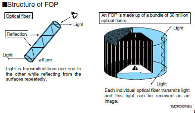
The FOP is an optical plate comprising some millions to hundreds of millions of glass fibers with 6 m diameter, bundled parallel to one another. The FOP is capable of transmitting an optical image from one surface to another without causing any image distortion.
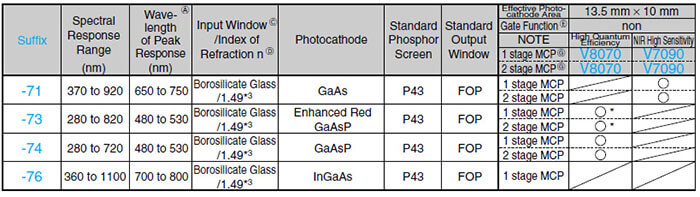
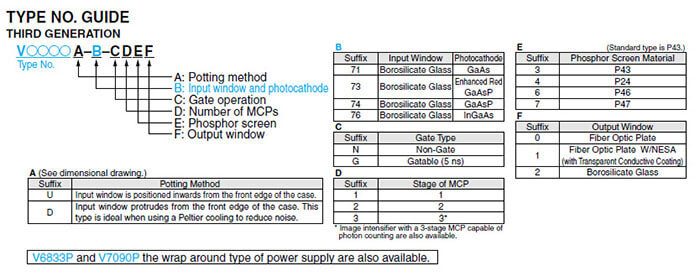
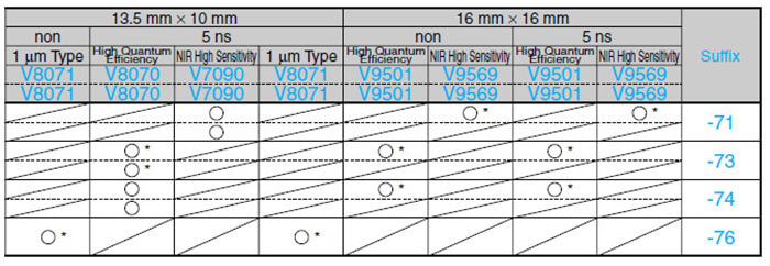
THIRD GENERATION
SECOND GENERATION
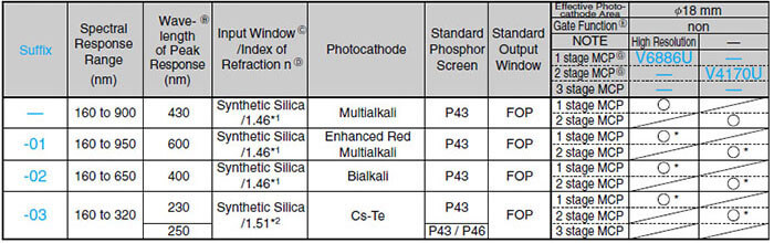
...Standard product ...Please consult with our sales office. *: Manufactured upon receiving your order
NOTE: A This number is for quantum efficiency.
B This number is for radiant sensitivity.
C Feel free to contact our sales office for availability of FOP or MgF2 input window. D Wavelength used measure refractive index: *1: 589.6 nm, *2: 254 nm, *3: 588 nm E Minimum gate time F Shutter time: Defined as the rise time. The input gate pulse width should be at least twice the shutter time.
G Image intensifier with a 3-stage MCP capable of photon counting are also available. Feel free to contact our sales office.
SECOND GENERATION
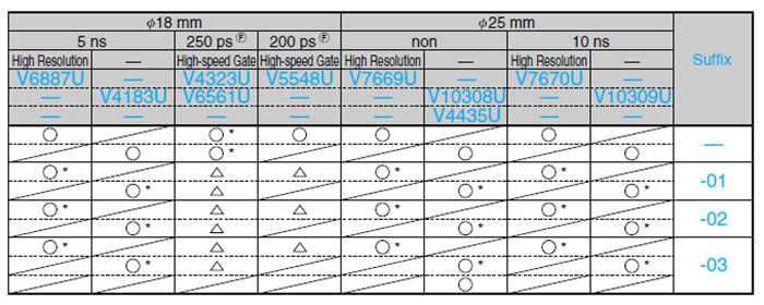
Hamamatsu second generation image intensifiers are classified by series type No. and suffix No. When you consult with our sales office about a product or place an order, please carefully refer to the characteristics listed in the spec table.
If you need custom devices (using a different window or phosphor screen material, low resistance MCP, transparent conductive film (NESA), special case potting), please let us know about your special requests.

CHARACTERISTICS
CHARACTERISTIC GRAPHS
WIRING DIAGRAM
Recommended Operation (Example)
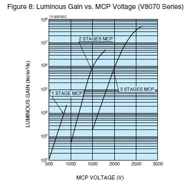
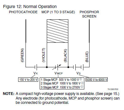
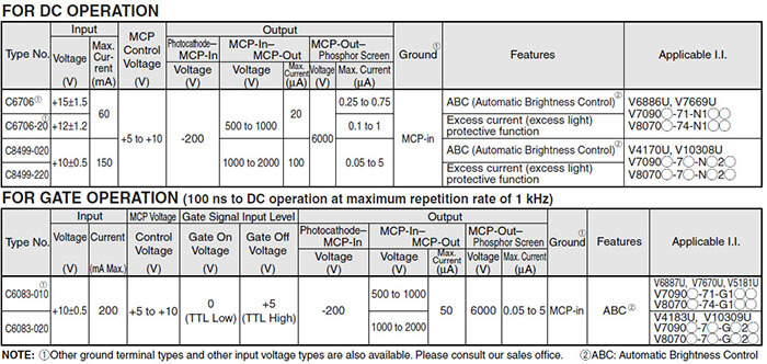
Supply Voltage (See Figure 12.)Photocathode – MCP-in (Vk) ...............................150 V to 200 V
MCP-in – MCP-out (VMCP)1 ....1 Stage MCP 500 V to 1000 V
2 1000 V to 1800 V
3 1500 V to 2700 V MCP-out –
Phosphor Screen (Vs) ...................5000 V to 6000 V
NOTE: 1The maximum supply voltage and recommended supply voltage for the MCP-in and MCP-out are noted on the test data sheet when the products is delivered. Please refer to the test data sheet for these values.
Gate Operation
There are two basic circuits for gate operation as shown in Figure 13 below. The supply voltages VMCP and Vs are the same as those in normal operation. Gate operation is controlled by changing the bias voltage (VB) between the photocathode and MCP-in.
Normally-OFF mode
The VB is constantly applied as a reverse bias to the photocathode, so no image appears on the phosphor screen. An image appears only when a gate pulse (VG) is applied to the photocathode.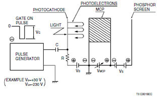
Normally-ON mode
The VB is constantly applied as a forward bias to the photocathode, so an image is always seen on the phosphor screen during operation. The image disappears only when a gate pulse (VG) is applied to the photocathode.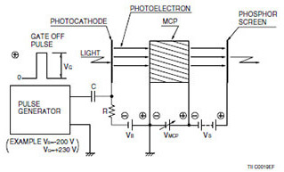
C, R: Chose the value in consideration of pulse width and repetition rate.
C: High voltage type.
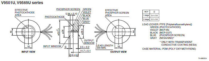
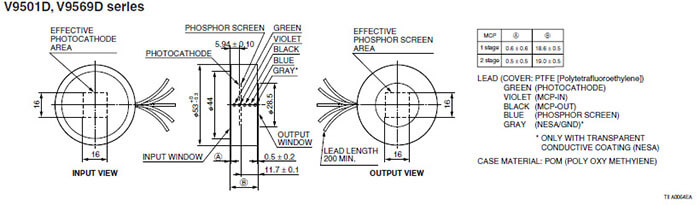
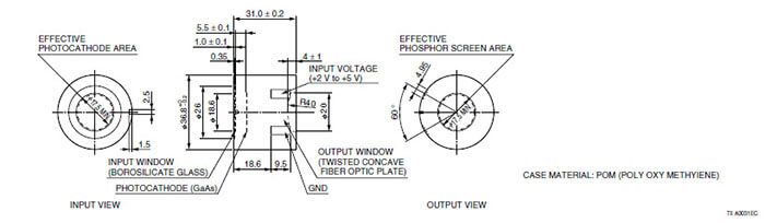
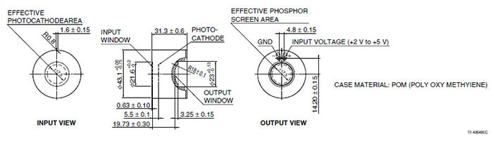
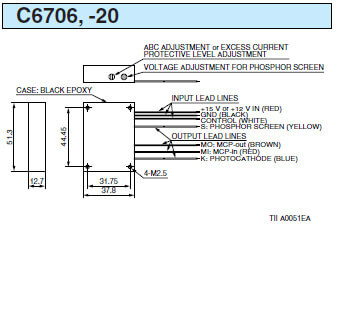
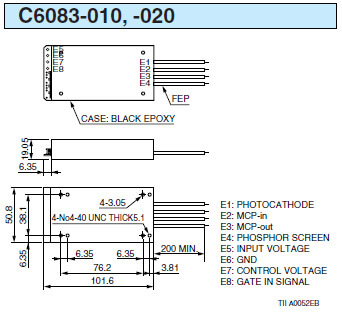
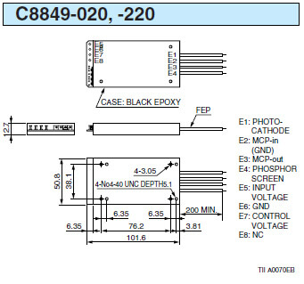
DIMENSIONAL OUTLINES
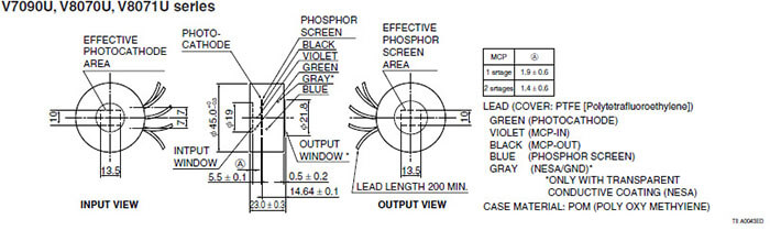
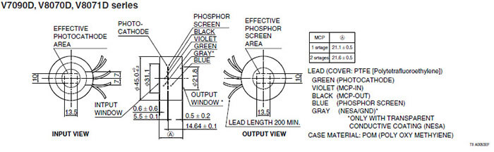
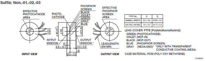
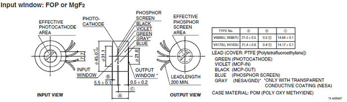
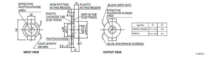
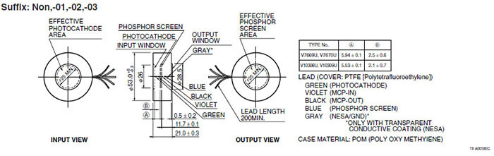
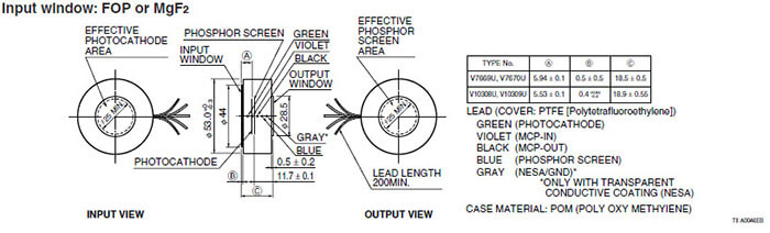
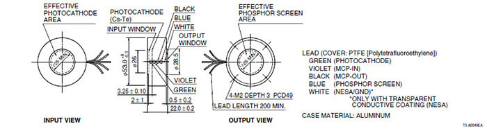
DIMENSIONAL OUTLINES
●HANDLING PRECAUTIONS AND WARRANTY
HANDLING PRECAUTIONS
●Do not apply excessive shocks or vibrations during transportation, installation, storage or operation. Image intensifiers are an image tube evacuated to a high degree of vacuum. Excessive shocks or vibrations may cause failures or malfunctions. For reshipping or storage, use the original package received from Hamamatsu.
●Never touch the input or output window with bare hands during installation or operation. The window may become greasy or electrical shocks or failures may result.
Do not allow any object to make contact with the input or output window. The window might become scratched.
●Dust or dirt on the input or output window will appear as black blemishes or smudges. To remove dust or dirt, use a soft cloth to wipe the windows thoroughly before operation. If fingerprints or marks adhere to the windows, use a soft cloth moistened with alcohol to wipe off the windows. Never attempt cleaning any part of image intensifiers while it is in operation.
●Never attempt to modify or to machine any part of image intensifiers or power supplies.
●Do not store or use in harsh environments. If image intensifiers is left in a high-temperature, salt or acidic atmosphere for a long time, the metallic parts may corrode causing contact failure or a deterioration in the vacuum level.
●Image intensifiers are extremely sensitive optical devices. When applying the MCP voltage without using an excessive light protective circuit, always increase it gradually while viewing the emission state on the phosphor screen until an optimum level is reached.
●Do not expose the photocathode to strong light such as sunlight regardless of whether in operation or storage. Operating the image intensifiers while a bright light (e.g. room illumination) is striking the photocathode, might seriously damage the photocathode. The total amount of photocurrent charge that flows in the photocathode while light is incident during operation has an inverse proportional effect on photocathode life. This means that the amount of incident light should be kept as small as possible.
●Never apply the voltage to image intensifiers exceeds the maximum rating. Especially if using a power supply made by another company, check before making connections to the image intensifier, that the voltage appling to each electrode is correct. If a voltage in excess of the maximum rating is applied even momentarily, the image intensifier might fail and serious damage might occur.
●Use only the specified instructions when connecting an image intensifier to a high-voltage power supply module. If the connections are incorrect, image intensifiers might be instantly damaged after the power is turned on. Use high-voltage connectors or solder having a high breakdown voltage. When soldering, provide sufficient insulation at the solder joint by using electrical insulation tape capable of withstanding at least 10 kV or silicon rubber that hardens at room-temperature and withstands at least 20 kV/mm.
WARRANTY
Hamamatsu image intensifiers are warranted for one year from the date of delivery or 1000 hours of actual operation, whichever comes first. This warranty is limited to repair or replacement of the product. The warranty shall not apply to failure or defects caused by natural disasters, misused or incorrect usage that exceeds the maximum allowable ratings.
When ordering, please double-check all detailed information.
SEPARATE POWER SUPPLIES
Hamamatsu offers various types of separate modular power supplies designed to provide the high voltages needed for image intensifier operation. These power supplies are compact, lightweight and operate on a low voltage input. Image intensifier gain is easily controlled by adjusting the control voltage for the MCP voltage or the control resistance. Please select the desired product that matches your application.
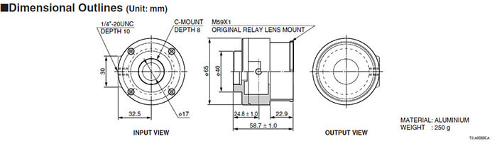
Dimensional Outlines (Unit: mm)
HOUSING CASE A10505
A10505 is a Housing case for easy to use 45mm outer diameter of Image Intensifier (output window: FOP, MCP: 1stage). It is available for 1 stage MCP type of V7090U/D, V8070U/D, V8071U/D, V6886U and V6887U series.
Input: C-mount, Output: Hamamatsu's relay lens mount. Screw hole for a tripod can be used for holding.
Dimensional Outlines (Unit: mm)
RELATED PRODUCTS
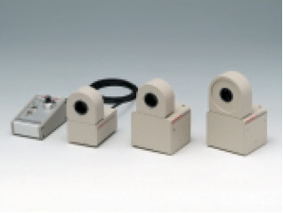
HIGH-SPEED GATED IMAGE INTENSIFIER UNITS
High-speed gated Image Intensifier (I.I.) unit comprises proximity focused I.I., high voltage power supply and gate driver circuit. Depending on application, a best gated I.I. unit can be selected from among various models.
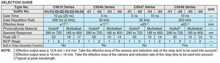
The built-in I.I. is available with GaAsP photocathode or Multialkali photocathode The Ga- AsP photocathode type delivers very high quantum efficiency in visible region ideal for bio- /fluorescence imaging application under a microscope. The Multialkali photocathode type offers a wide spectral range from UV (Ultra Violet) to NIR (Near Infrared Region). All of gated I.I. units can be operated and controlled from a remote controller or a PC (Per- sonal Computer) via a USB interface controller. HAMAMTSU also provides suitable relay lenses or CCD camera with FOP window for C9016/C9546 series.
C9548 series is released newly. This gated I.I. unit is added on a built-in pulse generator function and then it can be operatable at 500 ns min burst operation.
SELECTION GUIDE
ICCD CAMERA
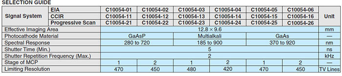
WITH HIGH-SPEED ELECTRONIC SHUTTER C10054 SERIES
The C10054 series is an easy to use compact camera housing an image intensifier fiber- coupled to a CCD, as well as a CCD drive circuit, high-voltage power supply and high- speed gate circuit. The C10054 series makes it easy to measure low-light-levels and capture images of various high-speed phenomena. A wide lineup of 18 models are currently provided allowing you to select multialkali, GaAs or GaAsP photocathodes the number of MCPs.
檔案下載