- HOME
- 產品介紹
- 半導體事業部
- Hamamatsu Photonics
- Camera
- sCMOS CAMERA
sCMOS CAMERA
![]() +886-2-8772-8910
+886-2-8772-8910
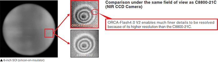
◎Sample images
| Product number | C11440-22CU | |
|---|---|---|
| Imaging device | Scientific CMOS sensor FL-400 | |
| Effective number of pixels | 2048 (H) X 2048 (V) | |
| Cell size |
6.5  m X 6.5 m m X 6.5 m |
|
| Effective area | 13.312 mm X 13.312 mm | |
| Full well capacity (typ.) | 30 000 electrons | |
| Readout time | Standard scan (at 100 frames/s) | 10 ms |
| Slow scan (at 30 frames/s) | 33 ms | |
| Readout noise | Standard scan (at 100 frames/s, typ.) | 1.6 electrons rms (1.0 electrons median) |
| Slow scan (at 30 frames/s, typ.) | 1.4 electrons rms (0.8 electrons median) | |
| Dynamic range (typ.)*1 | 37 000:1 | |
| Quantum efficiency | Over 70 % at 600 nm and 50 % at 750 nm | |
|
Cooling method |
Dark current (typ.) |
Sensor temp. (nominal) |
|---|---|---|
|
Forced air (Ambient at +20 °C) |
0.06 electrons/pixel/s |
–10 °C |
|
Water (+20 °C) |
0.02 electrons/pixel/s |
–20 °C |
|
Water (+15 °C) |
0.006 electrons/pixel/s |
–30 °C |
|
Readout speed |
Camera Link |
USB 3.0 |
|---|---|---|
|
Full resolution |
100 frames/s |
30 frames/s |
|
2048 ´ 1024 (at center position) |
200 frames/s |
60 frames/s |
|
2048 ´ 8 (at center position) |
25 655 frames/s |
7894 frames/s |
|
512 ´ 8 (at center position) |
- |
25 655 frames/s |
|
A/D conversion |
16 bit output |
|
|---|---|---|
|
Readout modes |
Digital binning 2 ´ 2 / 4 ´ 4 |
|
|
Sub-array readout mode |
||
|
Exposure time*2 |
Internal trigger mode (at full resolution) |
1 ms to 10 s |
|
Internal trigger mode with sub-array readout |
38.96 ms to 10 s |
|
|
External trigger mode with sub-array readout |
1 ms to 10 s |
|
|
Digital interface |
Camera Link *3 / USB 3.0 |
|
|
Lens mount |
C-mount / F-mount |
|
|
Power requirement |
AC 100 V to AC 240 V, 50 Hz/60 Hz |
|
|
Power consumption |
Approx. 70 VA |
|
|
Trigger in |
|
|---|---|
|
External trigger mode |
Edge, Level, Synchronous readout, Start trigger, Global reset edge and Global reset level |
|
External trigger signal routing |
SMA connector or Camera Link I/F |
|
External trigger delay function |
0 to 10 s in 10 ms steps |
|
Trigger out |
|
|---|---|
|
External signal output |
3 programmable timing outputs |
|
Global exposure timing and Trigger ready output |
|
|
External signal output routing |
SMA connector |
|
Software |
|
|---|---|
|
Software interface |
PC-based acquisition package included |
|
DCAM-SDK, commercially available software |
|
*1 Full well capacity / Readout noise median in slow scan
*2 Minimum exposure time in internal trigger mode varies depend on sub-array setting. Minimum exposure time is in standard scan.
*3 Proprietary mode equivalent of Camera Link 80-bit configuration
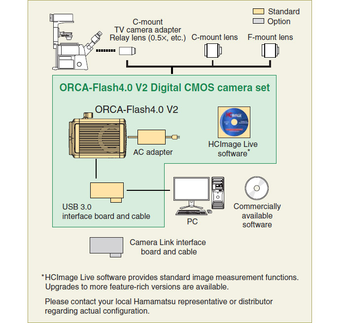
◎Configuration example
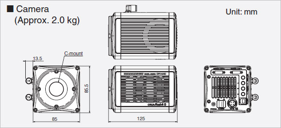
◎Dimensional outlines
●Introduction 4.0 V2
The digital camera ORCA Series has received favorable reception as a camera for scientific measurement for its high performance and quality. The digital camera ORCA-Flash 2.8 with the CMOS image sensor for scientific measurement has been added to the lineup, simultaneously achieving high-speed readout and low noise while having high resolution, allowing measurement in more extensive fields as compared with the conventional scientific measurement cameras.
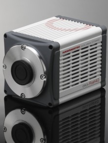
Thereafter, by adopting the state of the art CMOS image sensor FL-400 for scientific measurement, ORCA-Flash 4.0 has been developed, simultaneously achieving high sensitivity, high resolution, high-speed readout and low noise at higher levels. Moreover, we have launched the upgraded ORCA-Flash 4.0 V2 in 2013, adding new features to ORCA-Flash 4.0. The CMOS image sensor FL-400 for scientific measurement has excellent image quality and performance that overturns the concept of the conventional CMOS image sensor, and supports imaging and measurement in a wide range of optical regions from bright fields to weak fluorescence.
This technical documentation has been written not only to explain the features of ORCA-Flash 4.0 V2, but also for understanding of the characteristics of the sensor through introducing the basic technology of FL-400, so that the user can use the camera correctly and effectively.
●Basic Characteristics of FL-400 and ORCA-Flash
This chapter introduces basic characteristics such as the camera operation performance and technologies used in the CMOS image sensor FL-400 and ORCA-Flash 4.0 V2 for scientific measurement.
2.1.Structure of FL-400
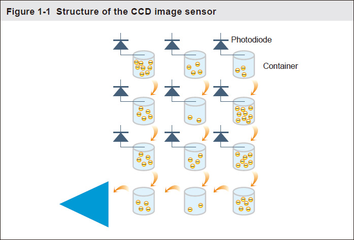
This section introduces a structural comparison of the CCD image sensor and CMOS image sensor (which has the same structure as FL-400), which are used for scientific measurement.
The pixels of the CCD image sensor consist of photodiodes and containers that accumulate electric charge. The incident light is converted into electric charge and accumulated in the container. The charge is carried by the bucket brigade method, and finally converted into voltage output. (See Fig. 1-1)
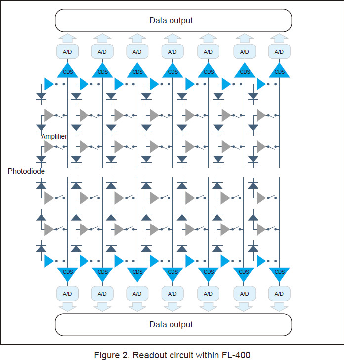
In contrast, the pixels of the CMOS image sensor consist of amplifiers that convert the photodiode and charge into voltage. The incident light is converted into electric charge, then converted into voltage within the pixel. The voltage for each pixel is output by sequentially switching the switches (see Fig. 1-2)
 |
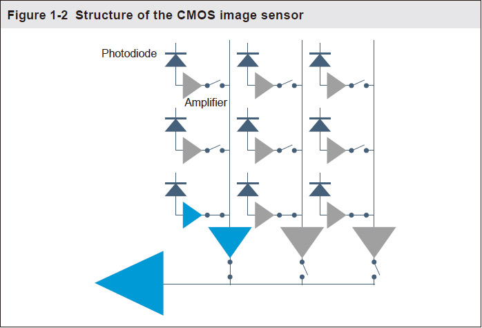 |
Figure 1. Structure of the CCD image sensor and CMOS image sensor
In addition, it has adopted an on-chip column amplifier / A/D to achieve higher speed, allowing the simultaneous parallel readout of one signal. This allows low-noise and high-speed signal readout.
Further, the element of FL-400 is divided into upper and lower, each of which is placed with an on-chip column amplifier / A/D. This allows the simultaneous readout of 2 horizontal lines, achieving higher speed. The image readout starts from 2 central lines, the upper one of which moves toward the upper end and the lower one toward the lower end.
|
|
 |
|
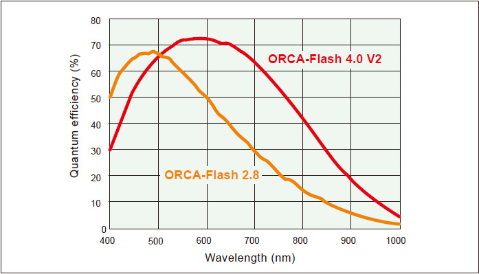
2.2. Quantum efficiency
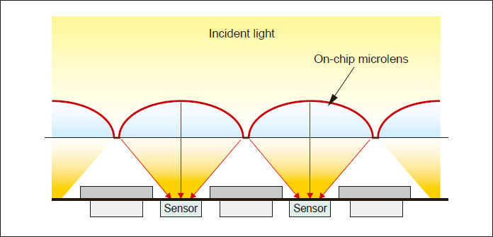
FL-400 converts the incident light into a charge in each pixel, and detects it as a signal. An important factor in determining sensitivity is the efficiency in converting light into electric charge, or quantum efficiency. Since FL-400 has multiple amplifiers arrayed in one pixel, the sensor unit that performs the light-to-charge conversion is limited to a part of the pixel. Therefore, by providing an on-chip microlens for each pixel, FL-400 has increased its utilization efficiency of light to achieve improved sensitivity. (See Fig. 3)
|
Further, by optimizing the element structure, the light utilization efficiency is increased, achieving increased sensitivity in comparison with the conventional CMOS image sensor (ORCA-Flash 2.8). (See Fig. 4)
|
|
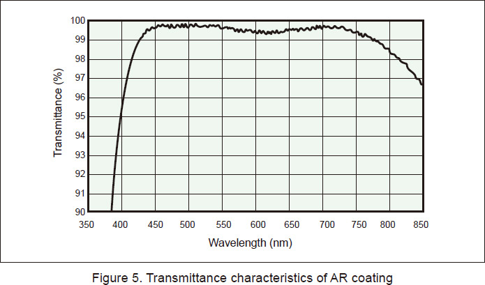
2.3. AR coating The input window of ORCA-Flash 4.0 V2 is a single window with double-sided AR coating, achieving 99 % or more transmittance at the wavelengths of 450 nm ~ 750 nm.
|
|
|
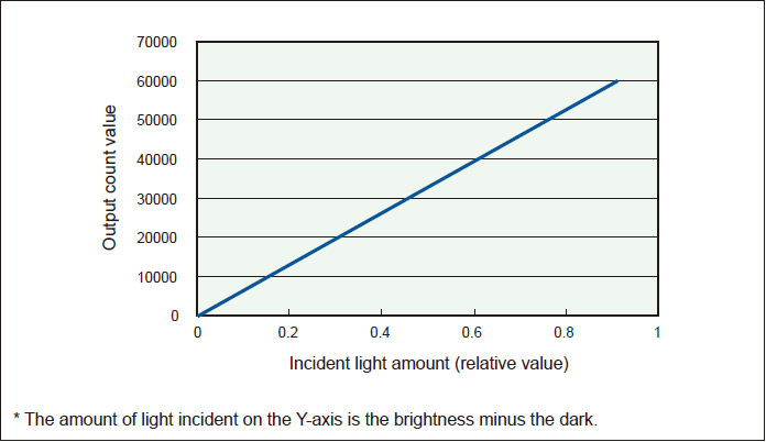
2.4. Linearity
To reliably detect the signal, the linearity of input-output characteristics is important. ORCA-Flash 4.0 V2 ensures the linearity of the amount of light incident into the pixel and signal output. This is achieved by the excellent linearity of the input and output characteristics of FL-400 as well as the optimally designed circuit. |
 |
2.5. Readout noise
The main factors that determine the detection limit of the image sensor are the dark current and readout noise of the sensor, important parameters that determine the performance of the camera.
Of the two, dark current can be reduced by cooling the sensor, making the readout noise the most important parameter.
2.5.1. What is readout noise?
It is the random noise generated within the charge-to-voltage conversion amplifier when reading out the charge.
2.5.2. Readout noise reduction method for FL-400
FL-400, using the latest CMOS technology, has greatly reduced the variations in the amplifier for each pixel as well as optimizing the pixel amplifier and increasing the gain. Further, by equipping a CDS circuit on the sensor, noise is dramatically reduced.
2.5.3. Readout noise measurement method
The CCD image sensor has one readout amplifier per sensor. Therefore, the readout noise measured by performing several readouts in each pixel and the readout noise measured in multiple pixels of one image are essentially equivalent. Therefore, the readout noise can be evaluated from a single image.
As FL-400 has an amplifier for each pixel, the readout noise is different for each pixel. Therefore, the readout noise is first measured for each pixel. The central value when the pixels are arranged from low to high noise is called the median. Compared to the average value, it represents the typical noise value unaffected by the maximum and minimum values. The rms noise is calculated from both the positive and negative errors with respect to the average value. It statistically represents the noise variation for each pixel.
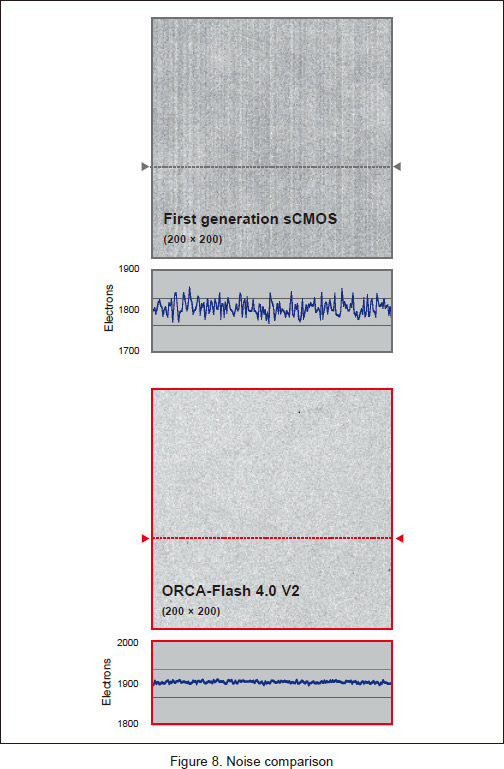
2.5.4. Readout noise performance of ORCA-Flash 4.0 V2
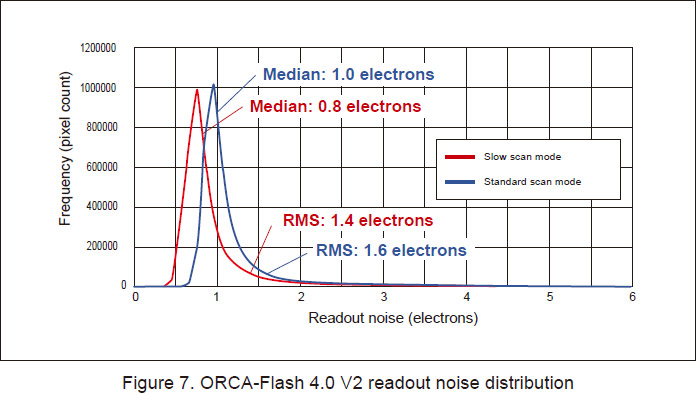
Figure 7 shows the frequency distribution of the readout noise in each pixel of ORCA-Flash 4.0 V2. It can be seen from the readout noise of 1.0 electron (median) and 1.6 electrons (rms) that pixels of very small values account for the majority. This achieves low readout noise as compared to the conventional cooling CCD image sensor. Moreover, this value is the performance for high-speed readout of 100 frames / second at 4 megapixels, which cannot be achieved by the CCD image sensor. In addition, in the slow scan mode that reduces noise, readout noise of 0.8 electrons (median) and 1.4 electrons (rms) has been achieved. * The slow scan mode will be described later. (3.1.2)
2.6. Dynamic range
The camera for scientific measurement represents the normal dynamic range as (saturation charge amount) / (readout noise). Therefore, considering the light amount equivalent of the readout noise as the minimum light amount that can be handled by the camera, the dynamic range means the ratio of the maximum light amount (= saturation charge amount) and minimum light amount (= light amount equivalent of readout noise) that can be handled by the camera. For ORCA-Flash 4.0 V2, with respect to the saturation charge amount of 30 000 electrons, the readout noise is 1.0 electrons (standard scan) and 0.8 electrons (slow scan). For this reason, the dynamic range has the high values of 30 000:1 (standard scan) and 37 000:1 (slow scan), which are equivalent to the values of a cooling CCD camera of slow scan type, which has the largest dynamic range for a conventional camera. Further, the dynamic range defined here is equivalent to the parameter represented as S/N for the conventional analog output camera. For this reason, using the following calculation formula, the dynamic range of digital cameras and S/N of analog output cameras can be converted.
Assuming the analog camera S/N as SNRa and digital camera dynamic range as D,
SNRa (dB) = 20 × log D
For example, if the dynamic range of ORCA-Flash 4.0 V2 is 37 000:1, the calculation will be as follows.
20 × log (37 000) = 91.4 dB
2.7. Dark current and cooling structure
The dark current of a CCD image sensor or CMOS image sensor is the charge generated due to the heat of the silicon from the sensor, one of the factors that determine the detection limit of the camera. Dark current has temperature dependency, which is known to drop the temperature by about 1/2 when the temperature of a CCD image sensor or CMOS image sensor drops by 7 °C to 8 °C. Therefore, cooling is a very effective means for suppressing dark current. Dark current depends on the type of CCD image sensor and CMOS image sensor, but FL-400 achieves an embedded photodiode similar to the CCD image sensor which realizes low dark current, allowing it to exhibit sufficient performance even at cooling temperature of -30 °C (water-cooling).
As the dark current value is stable compared with the value given the absence of cooling, the reproducibility of data is improved.
ORCA-Flash 4.0 V2 uses the Peltier element to cool FL-400 in order to suppress dark current to 0.006 electrons/pixel/s at the image sensor temperature of -30 °C (maximum water cooling) and 0.02 electrons/pixel/s at -20 °C (water-cooling). At this time, moisture in the atmosphere may condense when FL-400 is directly exposed to the atmosphere. To avoid this, the sensor has been isolated from the atmosphere with its interior filled with dry nitrogen.
|
Cooling method |
Cooling temperature |
Dark current (typ.) |
|---|---|---|
|
Air cooling (ambient temperature +20 °C) |
-10 °C |
0.06 electrons/pixel/s |
|
Water cooling (water temperature +20 °C) |
-20 °C |
0.02 electrons/pixel/s |
|
Maximum water cooling (water temperature +15 °C) |
-30 °C |
0.006 electrons/pixel/s |
2.8. High image quality (no fixed pattern noise)
ORCA-Flash 4.0 V2 can realize sufficient quality for scientific measurement by providing a high-quality image with a very low fixed pattern noise; the latter has been a major factor in lowering the image quality of the conventional CMOS image sensor. (See Fig. 8)
2.9. Real-time pixel correction function
For FL-400, a small amount of pixels exist with a larger readout noise compared to the surroundings. Thus, ORCA-Flash 4.0 V2 features a pixel collection function that replaces the pixel data with a large readout noise with the surrounding data for further improving the image quality. This correction is executed in real time to match the output speed of the camera, and therefore never slows down the frame rate. This function can also be turned ON / OFF.
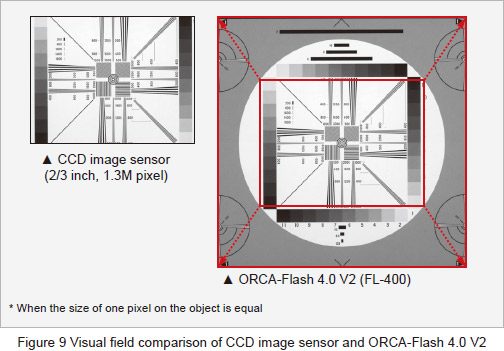
2.10. Pixel count and pixel size
FL-400 uses a pixel size of 6.5 μm x 6.5 μm, about the same as the widely used 2/3-inch 1.3 megapixel CCD image sensor. Since the number of pixels is over three times higher, a visual field three times wider can be observed compared to the 2/3-inch 1.3 megapixel CCD image sensor. (See Fig. 9)
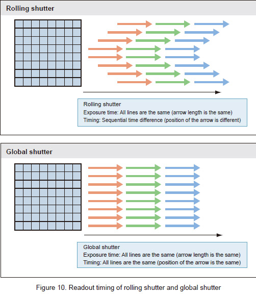
2.11.Rolling shutter / Global shutter
Exposure and readout method of the CMOS image sensor are classified into two types. They are rolling shutter and global shutter.
The rolling shutter is responsible for sequential exposure and readout with one pixel or one line as a single unit. For this reason, the exposure timing is different within one screen. (See Fig. 10)
Meanwhile, as the global shutter performs exposure and readout of all pixels at the same time, the exposure timing within one screen is simultaneous. (See Fig. 10)
Comparing the rolling shutter and global shutter, the readout noise and dark current can be kept lower when using the rolling shutter than the global shutter. As it is important that the readout noise and dark current characteristics are excellent when capturing dark images with less light, such as fluorescent images under a microscope, ORCA-Flash 4.0 V2 has adopted the rolling shutter. In addition, the rolling shutter is excellent in afterimage and smear characteristics.
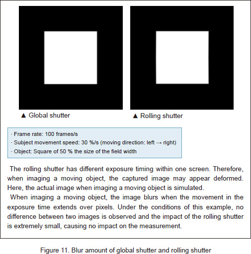
Furthermore, although the exposure timing of the rolling shutter within one screen differs, even if the target is moving, it has little effect on the actual measurement in most cases. (See Fig. 11)
2.12. Frame rate (readout speed)
The frame rate (readout speed) refers to the number of images that can be imaged in one second in continuous imaging, usually represented by frames/s (or fps). Whether imaging can be performed without a blur against the time resolution and moving subject is determined by the value of this frame rate, making it one of the important factors in selecting the camera.
FL-400 achieves both the low noise of 1.0 electron (median) and 1.6 electrons (rms), and the high frame rate of 100 frames/s (at 2048 × 2048 pixels) by simultaneous two-line parallel readout using the column A/D.
2.13. Readout mode
The readout modes of ORCA-Flash 4.0 V2 can be broadly divided into normal area mode and light sheet mode. Further information on each mode will be described later. (Chapter 3, 4)
●ORCA-Flash 4.0 V2 Normal Area Mode
This chapter introduces the normal area mode of ORCA-Flash 4.0 V2.
3.1. Readout method
There are various readout methods for ORCA-Flash 4.0 V2. Readout speed can be selected from the two types of standard scan and slow scan, and sub-array readout and binning readout can be used in combination for each scan mode.
3.1.1. Standard scan
In normal area mode, the readout of the center to upper part of the sensor is performed towards the upper end, and the lower part towards the lower end, sequentially performing readout from FL-400 for all pixels.
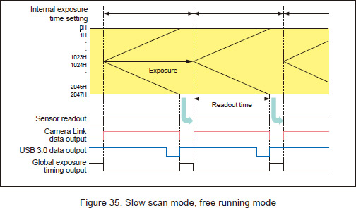
3.1.2. Slow scan
The slow scan mode can be used to reduce noise by extending the readout time of one horizontal line. It is an effective mode for applications that require less speed and lower noise. The standard scan mode (default setting) can be switched to the slow scan mode by a command.
3.1.3. Sub-array readout
The sub-array readout is a function that selects any area among all effective pixels and reads out only the signals of the selected part. By using this function, the readout time of one frame can be shortened, allowing the frame rate to be increased. While for the CCD image sensor, the area other than the selected part needs to sequentially transfer and discard charge and thus is limited in speed, FL-400 is capable of reading out only the necessary area. Therefore, the frame rate increases in inverse proportion to the reduction of the number of pixels. ORCA-Flash 4.0 V2 is capable of high-speed readout of up to 25 600 frames/sec using the sub-array readout function. In the sub-array readout, although the number of readout pixels is fewer, speed can be increased without adversely affecting readout noise. (See Table 2)
The configurable area is two vertically symmetrical positions centering on the center of the screen. When a single target area is used, the fastest readout is possible by setting the center of the screen.
Further, the configurable position and size are in 4-line increments.
|
Number of pixels in vertical direction |
Number of pixels in horizontal direction |
|||
|---|---|---|---|---|
|
Standard scan |
Slow scan |
USB 3.0 |
||
|
2048 |
512 |
1024 / 1536 / 2048 |
||
|
2048 |
100 |
30 |
100 |
30 |
|
1024 |
200 |
60 |
200 |
60 |
|
512 |
400 |
120 |
400 |
120 |
|
256 |
801 |
240 |
801 |
240 |
|
128 |
1603 |
481 |
1603 |
481 |
|
64 |
3206 |
962 |
3206 |
968 |
|
8 |
25 655 |
7696 |
25 655 |
7894 |
Table 2. Readout method, number of pixels and readout speed
3.1.4. Binning readout
Binning is a method of adding the signals of adjacent pixels to achieve high sensitivity at the cost of resolution. By performing binning, S/N can be improved without compromising the frame rate when capturing a dark image.
ORCA-Flash 4.0 V2 is capable of 2×2 or 4×4 binning. When performing 2×2 binning, the signal amount per pixel is quadrupled, and the number of output pixels will be 1024×1024. Note that ORCA-Flash 4.0 V2 performs digital processing (digital binning) within the camera. By using the binning function, the S/N can be improved.
2×2 binning improves the S/N by 2 folds, and 4×4 binning improves it by 4 folds.
|
Number of pixels in vertical direction |
Binning 2×2, 4×4 |
||
|---|---|---|---|
|
Camera Link |
USB 3.0 |
||
|
Standard scan |
Slow scan |
||
|
2048 |
100 |
30 |
30 |
|
1024 |
200 |
60 |
60 |
|
512 |
400 |
120 |
120 |
|
256 |
801 |
240 |
240 |
|
128 |
1603 |
481 |
481 |
|
64 |
3206 |
962 |
968 |
|
8 |
25 655 |
7696 |
7894 |
* The readout speed is when the center of the screen is measured (frames/s) Table 3. Readout speed of binning readout method
3.2. Camera operation modes
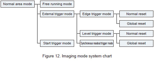
ORCA-Flash 4.0 V2 is equipped with various external synchronization functions and timing outputs that manage the imaging timing of a peripheral device and camera in order to achieve optimal imaging in a wide range of applications. Camera operation modes include the free running mode that allows the standalone operation of the camera and the external trigger mode that determines the exposure timing by an external trigger.
For details of timing, please refer to the "Timing charts" section below.
3.2.1. Free running mode
It is used when the camera does not work with an external device or when the exposure is made mainly by the camera. The free running mode allows operation at the frame rate of 100 frames/s (at all pixel readout), a rate higher than TV broadcasting, making it suitable for observation, visual field adjustment and video shooting. Further, where the target is dark, it is capable of imaging with the signal amount increased by lengthening the exposure time to raise the S/N. In this mode, the readout speed depends on the exposure time, which is expressed as Readout rate = 1 / Exposure Time. The maximum exposure time is 10 seconds.
3.2.2. External trigger mode
The external trigger mode synchronizes with a trigger signal from an external device. It is used when performing exposure. Also, by the use of external signals, the timing of exposure can be controlled in the edge trigger mode and level trigger mode.
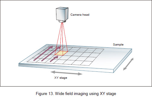
3.2.2.1. Edge trigger mode
The edge trigger mode is used when externally starting the exposure in synchronization with the rising / falling edge (rising and falling can be switched by a command) of the trigger signal. The exposure time is set on the camera by a command.
< Application example: Wide-field imaging > If the entire object to be measured is large and resolution is needed, imaging needs to be performed multiple times. When the target is moved on the XY stage and stage is stopped at the desired location, enter a trigger to the camera and perform the image capture. By repeating this process, an entire image of the object of interest can be obtained.
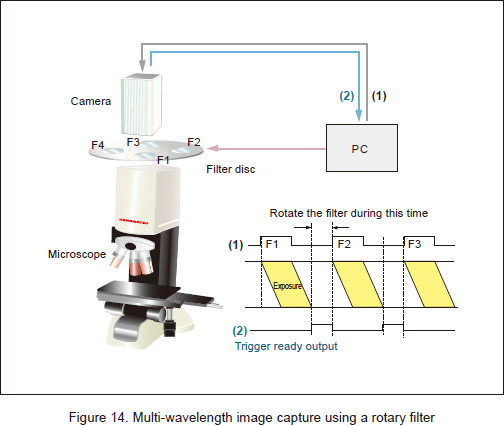
3.2.2.2. Level trigger mode
The level trigger mode performs the exposure for a period of Low / High of the external trigger signal (High and Low can be switched by a command). Since the exposure externally starts from the rising / falling edge of the trigger signal, the exposure start timing and exposure time can be externally controlled.
< Application example: High-speed multi-wavelength filter readout > When performing a multi-wavelength image capture using a rotary filter, by using the level trigger mode and trigger ready output (the trigger ready output will be discussed later), high-speed operation is made possible with controlled exposure time. The figure below is an example that uses four filters while controlling the exposure time of each filter on a PC (electrical signal control board).
When the filter F1 is fully prepared, the level trigger is entered on the camera. The figure shows the exposure beginning on the rising edge. The time until the fall is the exposure time. When the exposure is completed, a trigger ready signal is output from the camera. Along with it, rotate the filter and set the filter F2. This is the timing for switching a single filter.
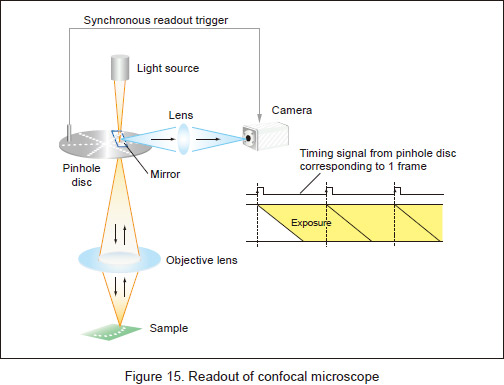
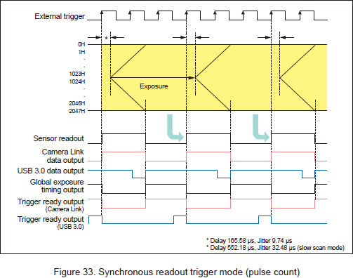
3.2.3. Synchronous readout trigger mode
The synchronous readout trigger mode externally starts the readout in synchronization with the rising / falling edge of the trigger signal (rising and falling can be switched by a command), then starts the next exposure after the readout. The exposure period is the interval between the edges of external trigger signals. Primarily, it is used for the pinhole disc type confocal microscope.
< Application example: Readout of confocal microscope > When performing a readout on a confocal microscope using a pinhole disc, high-quality imaging can be achieved by using the synchronous readout trigger. By capturing the data in accordance with the rotation timing of the pinhole disc, the uneven brightness caused by the fluctuation of rotational speed can be avoided. In this example, the rotation timing of the pinhole disc is detected by light, magnetism or the like, and is input into the camera. At the timing of the trigger input, the camera completes exposure and starts data readout and next exposure. If the signal from the pinhole disc is once per frame, the normal synchronous readout trigger mode is used. (It is also compatible in building one frame with multiple triggers.)
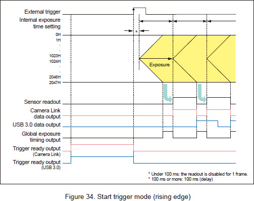
33.2.4. Start trigger mode
The start trigger mode externally starts the exposure in synchronization with the rising / falling edge of the trigger signal (rising and falling can be switched by a command.), then switches to the free running mode.
It is used when externally controlling the timing for starting image capture. It is especially effective in securing as much frame rate as possible while obtaining sensitivity. For example, when capturing a reaction being initiated with a stimulus, continuous image capture can be started in synchronization with the timing of the stimulation. Further, the free running mode allows the operation at the fastest frame rate, starting the exposure of the camera with the edge of the trigger signal input in the camera while simultaneously switching the camera to the free running mode.
< Application example: High-speed fluorescence imaging > In fluorescence imaging, with the exception of fluorescent dyes such as Q-DOT, the fading of fluorescence inevitably affects the measurement. The fluorescence begins to light from the moment the excitation light is shed, but its intensity gradually weakens. This is called fading. Generally, in fluorescence imaging, a shutter is placed in the optical path of the excitation light to prevent the excitation light from contacting the sample outside the imaging period of the camera, in order to prevent fading. By using the start trigger mode to start the image capture at the same time as opening the shutter, the effects of fading can be minimized. Also, as the start trigger mode switches to the internal synchronization mode once the trigger is accepted, image capture at the fastest frame rate is possible.
3.2.5. Global reset
In normal reset mode, the charge is reset after the readout ends for each horizontal line; then the exposure starts. After the series of operations is finished, it will proceed to the next horizontal line. Therefore, a readout time period delay of one horizontal line is generated for each horizontal line at the start of exposure.
The global reset function resets all lines at the same time. By using this function, the start of exposure can be aligned. Global reset can only be used in the edge trigger mode and level trigger mode.
3.2.6. External trigger delay function
For example, when starting the exposure at a predetermined time after the oscillation of the pulse laser, a delay unit is conventionally connected between the laser and camera to control the trigger signal.
ORCA-Flash 4.0 V2 allows the setting of delay time by a command to the trigger signal input in the camera in each external trigger mode. Therefore, even if there is no delay unit, it is capable of supporting various trigger signals.
3.3. External trigger output signal
In the normal area mode of ORCA-Flash 4.0 V2, the timing of exposure and the like can be output to the outside as a trigger signal. By using this output as trigger input for an external device, it can synchronously operate with external devices to match the timing of the exposure of the camera.
3.3.1. Global exposure timing output
All horizontal lines output the signals of High / Low in the period of exposure (High and Low can be switched by a command).
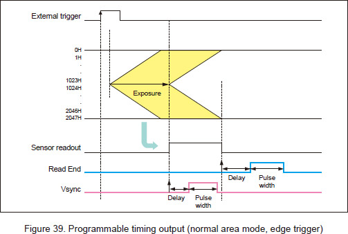
3.3.2. Programmable timing output
It is possible to program and output a pulse that has an optional pulse width and an optional delay time to the end of readout timing or Vsync.
3.3.2.1 Read End
Camera outputs a pulse after certain delay, from the end of sensor readout. Also the pulse width can be set.
3.3.2.2 Vsync
Camera outputs a pulse after certain delay, from the beginning of readout. Also the pulse width can be set.
3.3.3. Trigger ready output
The trigger ready output outputs a signal of High / Low when the readout is completed after the exposure of the camera, and the next external trigger can be input (High and Low can be switched by a command).
●ORCA-Flash 4.0 V2 Light Sheet Mode
4.1. Light sheet mode readout method
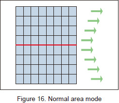
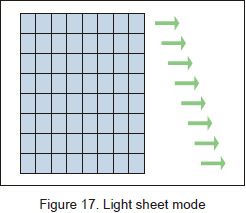
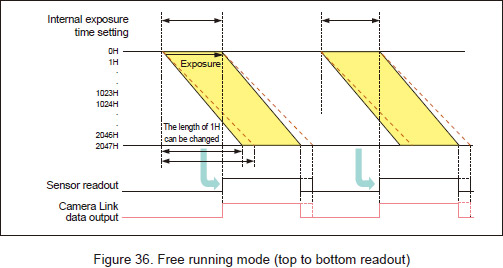
In normal area mode, the readout starts from two horizontal lines in the center of the sensor at the same time, one upper and lower line at a time. (Figure 16) In light sheet mode, the readout continues downward in order from the top line of the sensor. (Figure 17)
 |
 |
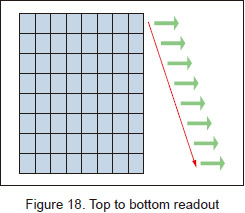
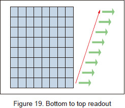
Further, readout can be switched between top to bottom, which reads out in the downward direction from the horizontal line on the top of the sensor, and bottom to top, which reads out in the upward direction from the horizontal line on the bottom of the sensor.
 |
 |
4.2. Light sheet mode imaging mode
Like the normal area mode, the light sheet mode includes the free running mode that allows the standalone operation of the camera and external trigger mode that determines the exposure timing by an external trigger.
For details of timing, please refer to the "Timing charts" section below. In the light sheet mode, only the camera link output is supported.
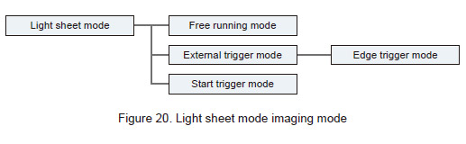
For each imaging mode, refer to 3.2 Imaging mode.
4.2.1. Light sheet free running mode
It is used when the camera does not work with an external device or when the exposure is made mainly by the camera.
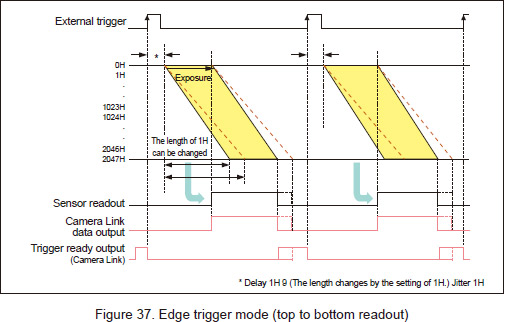
4.2.2. Light sheet edge trigger mode
The light sheet edge trigger mode synchronizes with an external trigger signal. It is used when performing exposure. The exposure time is set by a command.
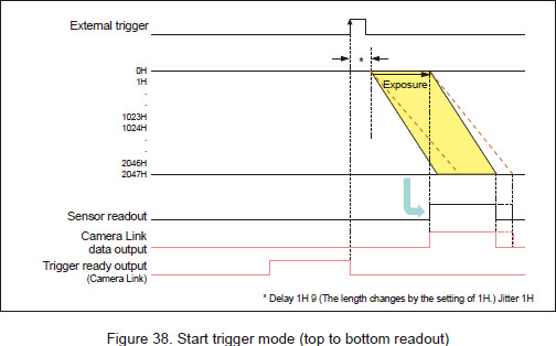
4.2.3. Light sheet start trigger mode
The start trigger mode is used when controlling the timing for externally starting the image capture.
4.3. Light sheet mode external trigger output signal
In the light sheet mode, programmable timing output and trigger ready output can be output to the exterior in the same way as the normal area mode. For the global exposure timing output and trigger ready output, see 3.3.1 and 3.3.3 of the Normal area mode respectively.
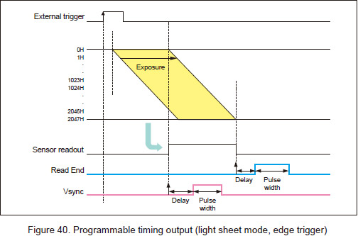
4.3.1. Programmable timing output
It is possible to program and output a pulse that has an optional pulse width and an optional delay time to the end of readout timing, Vsync or Hsync.
4.3.1. Programmable timing output
It is possible to program and output a pulse that has an optional pulse width and an optional delay time to the end of readout timing, Vsync or Hsync.
4.3.1.1 Read End
Camera outputs a pulse after certain delay, from the end of sensor readout. Also the pulse width can be set.
4.3.1.2 Vsync
Camera outputs a pulse after certain delay, from the beginning of readout. Also the pulse width can be set.
4.3.1.3 Hsync
Camera outputs a pulse after certain delay from the beginning of 1 row readout. Also the pulse width can be set.
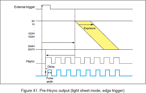
4.3.2. Pre-Hsync
When the reference signal of the programmable timing output is set to Hsync, pulses can be output in the number set by the user prior to starting the exposure. This is referred to as Pre-Hsync. The upper limit of the Pre-Hsync value to be set is determined by the trigger delay that is set by a command.
●5Connection with the Computer
5.1.Output / control interface
ORCA-Flash 4.0 V2 is equipped with a Camera Link interface and USB 3.0 interface as the image output and control interfaces. Note that since the interface connected to the camera is automatically enabled, manual switching is not required.
5.1.1. Camera Link interface
When connecting with the Camera Link interface, images of 4 megapixel and 16-bit each can be transferred to a personal computer in 100 frames/s (full frame). The readout of an entire image starts from the center toward the upper and lower ends, such as from the 1024th horizontal line toward the 1025th and 1023th lines.
|
Standards |
Camera Link 80-bit configuration equivalent |
|---|---|
|
Pixel clock |
85 MHz |
|
Pixel output |
16-bit × 5 pixels/clock |
5.1.2. USB 3.0 interface
The USB 3.0 interface is a general-purpose interface with a maximum speed of 500 MB/sec. It comes standard with many personal computers, and is equipped in many notebook computers.
5.2. Application software and driver software ORCA-Flash 4.0 V2 is supported by DCAM-API, which is provided as driver software. DCAM-API supports many of our digital cameras for scientific measurement as well as ORCA-Flash 4.0 V2, and is designed to absorb the difference in their properties and to allow control by a common calling method.
For detailed information such as compatible OS, I/F card and application software, please contact the sales representative.
Note that just as the 64-bit version is recommended for the OS, the 64-bit compatible version is recommended for the application software.
●Specifications
6.1. Camera performance
|
Model name |
C11440-22CU |
|||||
|---|---|---|---|---|---|---|
|
Imaging element |
CMOS image sensor for scientific measurement FL-400 |
|||||
|
Effective pixels |
2048 (H) × 2048 (V) |
|||||
|
Pixel size |
6.5 μm (H) x 6.5 μm (V) |
|||||
|
Effective element size |
13.312 mm (H) x 13.312 mm (V) |
|||||
|
Readout mode |
Standard scan mode |
Slow scan mode |
||||
|
Readout time |
10 ms |
33 ms |
||||
|
Readout noise (typ.) |
1.0 electrons (median) |
0.8 electrons (median) |
||||
|
Readout speed |
Camera Link |
USB 3.0 |
Camera Link/USB 3.0 |
|||
|
All-pixel reading 2048×1024 (1) |
100 frames/s |
30 frames/s |
30 frames/s |
|||
|
200 frames/s |
60 frames/s |
60 frames/s |
||||
|
25 655 frames/s |
7894 frames/s |
7696 frames/s |
||||
|
Binning (2) |
2×2, 4×4 |
|||||
|
Sub-arrays |
Possible (1) |
|||||
|
Saturation charge amount (typ.) |
30 000 electrons |
|||||
|
Dynamic range (3) |
37 000:1 |
|||||
|
S/N |
91 dB |
|||||
|
Cooling method (Peltier cooling) |
Sensor temperature |
Dark current (typ.) |
||||
|
Cooling temperature / dark current |
Air cooling Water cooling |
-10 °C (Room temperature: +20 °C) |
0.06 electrons/pixel/s |
|||
|
Maximum water cooling |
-30 °C (Water temperature: +15 °C) |
0.006 electrons/pixel/s |
||||
|
A/D output |
16 bit |
|||||
|
Linearity |
γ=1±0.03 |
|||||
|
Exposure time |
Free running mode |
1 ms to 10 s (at full pixel readout) (4) |
||||
|
Free running sub-arrays |
38.96 μs to 10 s |
|||||
|
External trigger / sub-arrays |
1 ms to 10 s |
|||||
|
External trigger mode |
Edge trigger (normal, global reset), level trigger (normal, global reset), synchronous readout trigger, start trigger |
|||||
|
Trigger delay function |
0 μs to 10 s (10 μs steps) |
|||||
|
Trigger output |
Global exposure timing output Programmable timing output × 3 Trigger ready output |
|||||
|
Lens mount |
C-mount |
|||||
|
Interface |
Camera Link 80-bit configuration equivalent (5)/ USB 3.0 |
|||||
|
Camera Link output clock |
85 MHz |
|||||
|
Connector specifications |
Mini-Camera Link |
|||||
|
Trigger connector specifications |
SMA |
|||||
|
Power supply |
100 VAC to 240 VAC, 50 Hz / 60 Hz |
|||||
|
Power consumption |
Approx. 70 VA |
|||||
|
Storage ambient temperature |
-10 °C to +50 °C |
|||||
|
Operating ambient temperature |
0 °C to +40 °C |
|||||
|
Operating ambient humidity |
70 % or less (no condensation allowed) |
|||||
(1) The setting area for achieving the fastest frame rate is the vertically symmetrical area centered on the middle of the screen. For areas other than the horizontal direction and non-central portions of the screen, it is achieved in combination with DCAM.
(2) Digital processing (digital binning) is performed within the camera.
(3) It is the calculation result of the saturation charge amount / readout noise (in slow scan mode, at median).
(4) When using the sub-array readout mode in the free running mode, the minimum exposure time will vary depending on the sub-array size and location.
(5) It is an original output based on the 80-bit configuration of Camera Link.
6.2. Operating ambient temperature and humidity
The operating environment temperature is very important for electrical devices and equipment. This is because when the camera is used outside of the temperature range, its performance will not be guaranteed and failures may result. This is more important for cooling CCD and CMOS cameras, especially of air-cooling type, as the operating environment temperature affects the cooling temperature of the camera, which may lead to an increase of dark current noise. In general, the camera head is often placed in a room covered with a blackout curtain or inside a dark box to block the light when using a high-sensitivity camera, which may reduce the air flow and increase the temperature. The controller is also often placed in the corner of a room where the air flow is poor, where the temperature may be higher than the room temperature. The operating environment temperature of ORCA-Flash 4.0 V2 is set widely at 0 °C to +40 °C, wider than the normal room temperature of +20 °C to +30 °C, allowing it to be used with confidence.
Humidity is also important. The higher the ambient humidity, the more likely it is for condensation to occur. In particular, if the camera has a cooling function and parts of which the temperature becomes lower than the environment temperature, the ambient humidity will also be important.
It is recommended for ORCA-Flash 4.0 V2 to be used in a non-condensing environment with humidity of 70 % or less.
6.3. Safety standards and applicable standards
CE Marking
EMC Directive Applicable Standards
EN61326-1: 2006 Class A
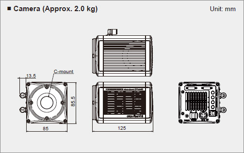
6.4. Outline dimension drawings
●S/N of CMOS and EM-CCD for Scientific Measurement
This chapter compares the CMOS for scientific measurement and electron multiplying CCD (EM-CCD) used in conventional low-light-level measurement, regarding S/N as a very important factor in performing scientific measurement by camera.
7.1. S/N calculation formula
In considering the S/N of the CMOS for scientific measurement and EM-CCD, the key factors are the input light amount, quantum efficiency and EM gain of the input signal, and the photon shot noise, noise factor, and readout noise etc. of the noise.
7.1.1. Input signal
a ) Amount of input light (P)
The CMOS for scientific measurement and EM-CCD differ in pixel size. However, as we will be essentially discussing the S/N, the pixel area will not be taken into account. The amount of incident light will be examined by the photon amount (number of light particles) incident to one pixel . Note that, by changing the optical magnification in the two cameras for measurement, the number of photons incident to one pixel can be equalized.
b ) Quantum efficiency (QE)
This is the efficiency in converting light into electric charge.
c ) EM gain (M)
This represents the multiplication of the charge in EM-CCD. The maximum gain of EM-CCD is 1200 and that of CMOS for scientific measurement is 1.
Thus, the input signal detected in one pixel is the following.
S = P × QE × M
7.1.2. Noise
d ) Photon shot noise
It is the noise caused by fluctuation when the incident light is converted into charge.

e ) Noise factor (Fn)
EM-CCD performs charge multiplication using the multiplication register in the element. The noise caused by the impact of this charge multiplication is called excess noise. The coefficient of excess noise is statistically calculated to be ![]() Note. that as the CMOS for scientific measurement has no charge multiplication, the coefficient is 1.
Note. that as the CMOS for scientific measurement has no charge multiplication, the coefficient is 1.
f ) Readout noise (Nr) It is the noise caused by reset on the charge-to-voltage conversion amplifier of the CMOS for scientific measurement and EM-CCD.
g ) Background light (Ib)
Assuming the situation where the object light overlaps the background light, the noise caused by the background light is also considered.
h ) Dark current (Id)
For CMOS for scientific measurement and EM-CCD, a signal that occurs even without incident light, or dark current exists.
Therefore, the sum total of the noise will be as follows.

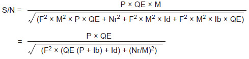
7.1.3. S/N
Calculating the S/N from the results of 3.1.1 Input signal and 3.1.2 Noise, the equation will be as follows.
7.1.4. EM-CCD excess noise
In the theoretical formula of S/N, if the EM gain of EM-CCD is large enough, the item (Nr / M)2 can be ignored. Also, assuming that there is no background light and the exposure time is short, S/N can be described as follows.
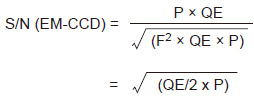
Also, where the amount of incident light is sufficient and readout noise can be ignored, S/N of CMOS for scientific measurement will be as follows.
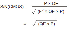
Comparing the S/N formula of EM-CCD and CMOS for scientific measurement, the quantum efficiency of EM-CCD is multiplied by the coefficient of 1/2. This signifies that the quantum efficiency of EM-CCD is equivalent to half, due to the effect of excess noise where the light is sufficient.
7.2. Comparison of S/N
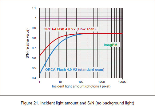
7.2.1. CMOS vs. EM-CCD for scientific measurement without background light
Figure 21 represents the S/N of CMOS for scientific measurement and EM-CCD when the amount of incident light is changed. Note that S/N here is the relative value with an ideal device with 100% quantum efficiency and 0 noise as the reference.
The target camera is ORCA-Flash 4.0 V2 (CMOS for scientific measurement) and ImagEM (EM-CCD). The setting conditions are EM-CCD EM gain × 1200, exposure time 30 ms and the same amount of light per pixel.
In this case, when the amount of light exceeds 2 photons / pixel (at slow scan), the S/N of ORCA-Flash 4.0 V2 exceeds that of ImagEM.
7.2.2. CMOS vs. EM-CCD for scientific measurement with background light
When imaging, there are cases where only the object light is present and those where a background light is present and the object light overlaps therewith. In many cases of fluorescence imaging of cells, a background light is present. Where a background light is present, the S/N is also considered.
Figure 22 shows how S/N changes with respect to the incident light intensity if the background light is 10 photons / pixel.
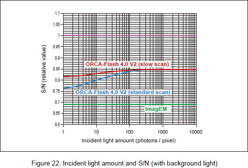
In this context, for any amount of light, the S/N of ORCA-Flash 4.0 V2 exceeds that of EM-CCD.
Figure 23 represents how S/N changes when the background light amount changes at the incident light amount of 5 photons.
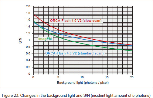
In Figure 23, it can be seen that S/N of ORCA-Flash 4.0 V2 exceeds that of EM-CCD when the background light exceeds 1 or 2 photons.
7.2.3. Comparison results of CMOS and EM-CCD for scientific measurement in the weak light range
As ORCA-Flash 4.0 V2 has high quantum efficiency, low readout noise and noise factor of 1, it has sensitivity comparable to that of EM-CCD. Especially in the weak light range (> 2 or 3 photons / pixel), in addition to S/N being better than EM-CCD, imaging in a wide field of view is possible. It is also capable of reading out at a high-speed frame rate.
Conventionally, in low-light imaging such as fluorescence imaging, CCD or EM-CCD has been used. However, in much of fluorescence imaging, the amount of light is more than 2 or 3 photons / pixel. For this reason, in much of low-light imaging, ORCA-Flash 4.0 V2 can be introduced instead. Also, background light is present in much fluorescence imaging.
When the amount of incident light is 10 photons / pixel, if the background light is more than one photon, S/N of ORCA-Flash 4.0 V2 exceeds that of EM-CCD.
EM-CCD has no background light and can achieve the best S/N in a very dark light intensity (< 2 or 3 photons / pixel).
●Various Timing Charts
8.1. Explanation of timing charts
In Chapter 8, each imaging mode is described with reference to a timing chart. First, the chapter discusses how to read the timing charts.
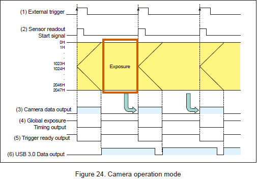
The horizontal axis in Figure 24 represents the passage of time. The part colored in yellow represents the exposure condition of the CMOS sensor. The top of the figure represents the top of the screen of the CMOS sensor, and the bottom of the figure represents the bottom of the screen of the CMOS sensor. As the CMOS sensor controls the exposure in one horizontal line increment, the transverse timing of the CMOS sensor is omitted in the figure. This figure is when the external trigger is input.
After inputting an external trigger (1), a sensor readout (readout of the data in the previous frame) is started (2), and the center lines (1023H, 1024H) of the screen will start exposing at the same time. The camera data output also begins with the start of the sensor readout. (3)
With the passage of time, the sequential readout of previous frames on a line-by-line basis and exposure of the next frame start.
In the period where all lines are exposed (red square in the figure), the global exposure output (4) is output. Also, a trigger ready output (5) will be output once the readout of one frame is completed and the next external trigger reception is enabled, and if a USB 3.0 is connected, USB 3.0 data output will be output (6).
8.2. Normal area mode
8.2.1. Free running mode
ORCA-Flash 4.0 V2 allows the exposure time to be set by an external command and is equipped with free running mode that operates in the camera itself. The free running mode is equipped with the normal readout mode (when the exposure time is longer than the readout time of one frame) and electronic shutter mode (when the exposure time is shorter than the readout time of one frame). These modes automatically switch according to the exposure time setting.
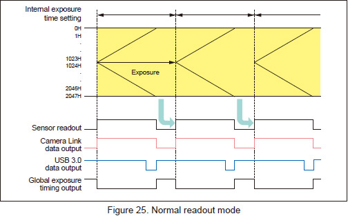
8.2.1.1. Normal readout mode
The normal readout mode is a mode where the set exposure time is either the same as or longer than the readout time. If the exposure time is set to be equal or longer than the readout time for one frame, the global exposure timing output signal will be output when exposure starts for the period in which the exposure is performed in all pixels. When the exposure ends and readout of the sensor starts, the camera data is output at the same time as the sensor readout start signal is output.
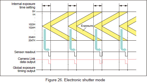
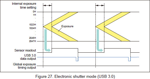
8.2.1.2. Electronic shutter mode
The electronic shutter mode is used for imaging with a suitable signal level when the light intensity is too high and output signal overflows in the normal readout mode. Although the exposure time is shorter than one frame, the frame rate is 100 frames/s (when reading out all pixels). Although the basic timing is the same as the normal readout mode, because the exposure time is short, the global exposure timing output will not be output.
8.2.2. External trigger mode
As an external device becomes the master when performing image capturing in synchronism with the external device, ORCA-Flash 4.0 V2 is equipped with various external trigger modes in which the camera becomes the slave.

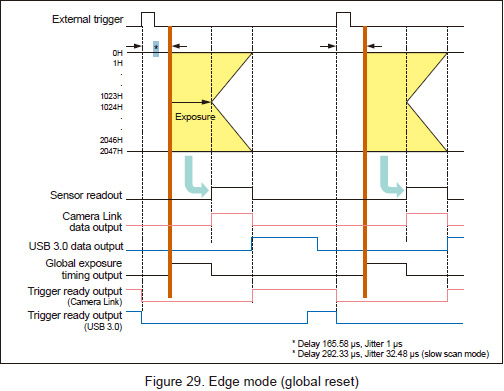
8.2.2.1. Edge trigger mode (global reset)
In the edge trigger mode, the global reset is made by the edge (rising / falling edge) of the trigger signal input to the camera. At the same time, global exposure is started, and the readout is done by normal readout. The timing other than the reset is the same as the edge trigger mode (normal reset).
8.2.2.1. Edge trigger mode (global reset) In the edge trigger mode, the global reset is made by the edge (rising / falling edge) of the trigger signal input to the camera. At the same time, global exposure is started, and the readout is done by normal readout. The timing other than the reset is the same as the edge trigger mode (normal reset).
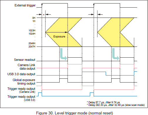
8.2.2.2. Level trigger mode (normal reset)
The level trigger mode is used when performing exposure in synchronization with an external trigger signal and externally controlling the exposure time with a trigger signal.
The level trigger mode is a mode where the exposure starts when the input trigger signal switches from Low to High (or High to Low), and continues until the end of the period of High (or Low). An example of the "High" trigger level is shown below. When the trigger signal goes to High, the exposure of the central lines (1023H, 1024H) starts, then after the readout time of one line, exposure of the next line starts, after which each line successively starts exposure. The exposure of the first line stops at the moment the signal level goes to Low to start the readout of the signal. The exposure time of each line is the time from when the trigger level goes to High until it goes to Low.
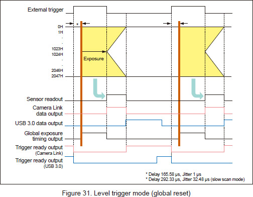
8.2.2.3. Level trigger mode (global reset)
In the global reset, the level trigger mode is a mode where the global reset is performed and exposure is started when the input trigger signal switches from Low to High (or High to Low), and the exposure continues until the end of the period of High (or Low). As with the edge trigger mode, the readout is done by normal readout. The timing other than the reset is the same as the level trigger mode (normal reset).
8.2.2.4. Synchronous readout trigger mode
In the synchronous readout trigger mode, the exposure of the camera is ended and readout is started, and the next exposure is simultaneously started by the edge (rising / falling edge) of the trigger signal input to the camera. That is, the exposure time will be the interval between the edges of an external trigger.
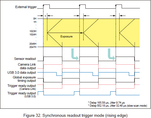
Also, the synchronous readout trigger mode is capable of pulse count readout where the readout is performed once per any number of input triggers. The figure below is an example where one readout is made with respect to three input triggers.
8.2.2.5. Start trigger mode
The start trigger mode is a mode that captures continuous images with one external trigger pulse, and as it operates in free running, it is capable of operating at the fastest frame rate.
In the start trigger mode, the exposure of the camera is started at the same time as the camera is switched to the free running by the edge (rising / falling edge) of the trigger signal input to the camera.
8.2.2.6. Slow scan mode
In the slow scan mode, the readout slope is changed from 10 ms to 30 ms, and the fastest frame rate is 30 frames/s. As there is no change in the relationship of each trigger input and output other than the readout slope, please see the timing diagrams of Figure 25 to 34 for the standard scan.
8.3. Light sheet mode
8.3.1. Free running mode
As with the normal area mode, it allows the exposure time to be set by an external command and is equipped with free running mode that operates within the camera itself. In the free running mode, the exposure time and readout direction can be set by an external command. In the top to bottom readout, exposure is performed from line 0H of the sensor top to 2047H in 1H increments. When the exposure ends, readout continues sequentially from line 0H.
8.3.2. Edge trigger mode
In the edge trigger mode, exposure is made sequentially from 0H by the edge (rising / falling edge) of the trigger signal input to the camera. When the exposure ends, readout is performed by each horizontal line.
8.3.3. Start trigger mode
The start trigger mode is used when controlling the timing for externally starting the image capture as with the normal area mode. In the start trigger mode, the exposure of the camera is started at the same time as the camera is switched to the free running by the edge (rising / falling edge) of the trigger signal input to the camera.
8.4. Trigger output
In order to synchronize the camera with an external device, ORCA-Flash 4.0 V2 is equipped with various trigger output signals in which the camera becomes the master and the external device the slave.
8.4.1. Global exposure timing output
It outputs the period where all lines are exposed simultaneously. Since the exposure timing in each line is different for the rolling shutter, a phenomenon may be observed separately in two frames, but by utilizing the timing where all lines are simultaneously exposed such as in long-time exposure, global exposure will be enabled for phenomena that occur in this period. For more information on the timing, please refer to Figures 25 to 35. Please note that the global exposure timing output is not output in the light sheet mode.
8.4.2. Programmable timing output For the programmable timing output, pulses with a delay time and pulse width as set by a command, and that pulse based on the end of the sensor readout, Vsync (vertical synchronous signal) or Hsync (horizontal synchronous signal) will be output.
By using the programmable timing output, simple synchronization with external devices will be enabled, allowing it to replace a simple delay unit or pulse generator.
The setting range of time delay is 0 μs to 10 s and pulse width is 1 μs to 10 s.
8.4.3. Pre-Hsync
Pulse can be output only prior to starting the exposure when the reference signal of programmable timing output is set to Hsync. The upper limit of the Pre-Hsync value to be set is determined by the trigger delay that is set by a command. This output is enabled only in the light sheet mode.
8.4.4. Trigger ready output
When operating in the external trigger mode, the interval from one exposure to the next can be shortened with the use of the trigger ready output.
When the camera is operating in the external trigger mode, for example for the edge trigger, the next exposure can start only after the sensor readout has ended. For this reason, a trigger for the next start of exposure cannot be accepted during an exposure or readout. By outputting that, the camera can start exposing and inputting a trigger to the camera at the same time, reducing the dead time as much as possible. In this way, a trigger ready output outputs that the camera is in a state where a trigger can be accepted.
檔案下載