- HOME
- 產品介紹
- 半導體事業部
- Hamamatsu Photonics
- Mass spectrometry
- Electron multipliers (EM)
Electron multipliers (EM)
![]() +886-2-8772-8910
+886-2-8772-8910
| ● GAIN characteristics | |
| Electron multipliers are mainly used as positive/negative ion detectors. They are also useful for detecting and measuring vacuum UV rays and soft X-rays. Hamamatsu electron multipliers have a high gain (multiplication factor) yet low dark current, allowing operation in photon counting mode to detect and measure extremely small incoming particles and their energy. This means our Hamamatsu electron multipliers are ideal for electron spectroscopy and vacuum UV spectroscopy such as ESCA (electron spectroscopy for chemical analysis) and Auger electron spectroscopy as well as mass spectroscopy and field-ion microscopy. |
 |
|
Type No. |
Structure |
Number of stages |
Material |
Input aperture size |
|
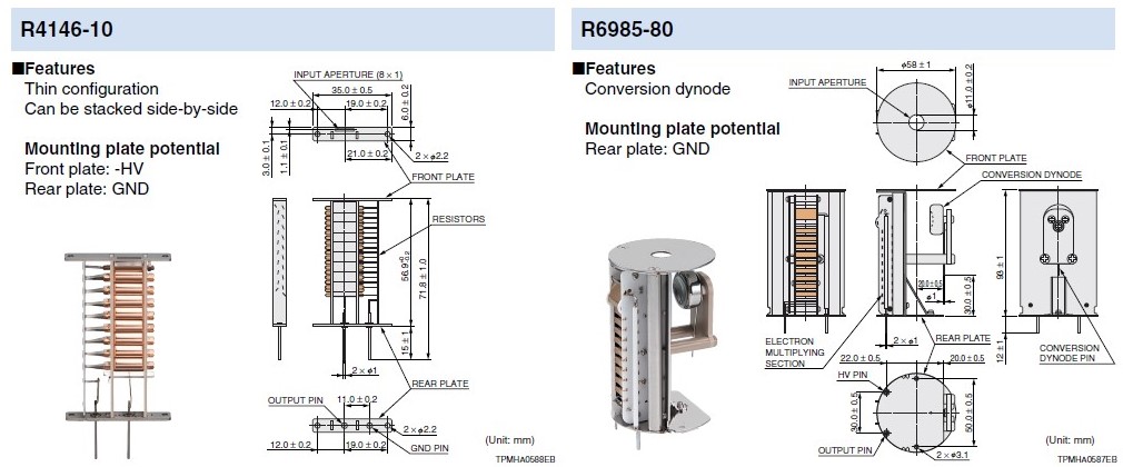
R4146-10 |
Linear-focused |
18 |
Cu-BeO |
8 x 1 |
|
R6985-80 |
Box-and-line |
19 |
Al2O3 |
φ11 |
|
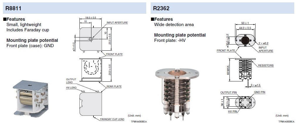
R8811 |
Circular-cage |
13 |
Al2O3 |
φ3 |
|
R2362 |
Coarse mesh |
23 |
Cu-BeO |
φ20 |
|
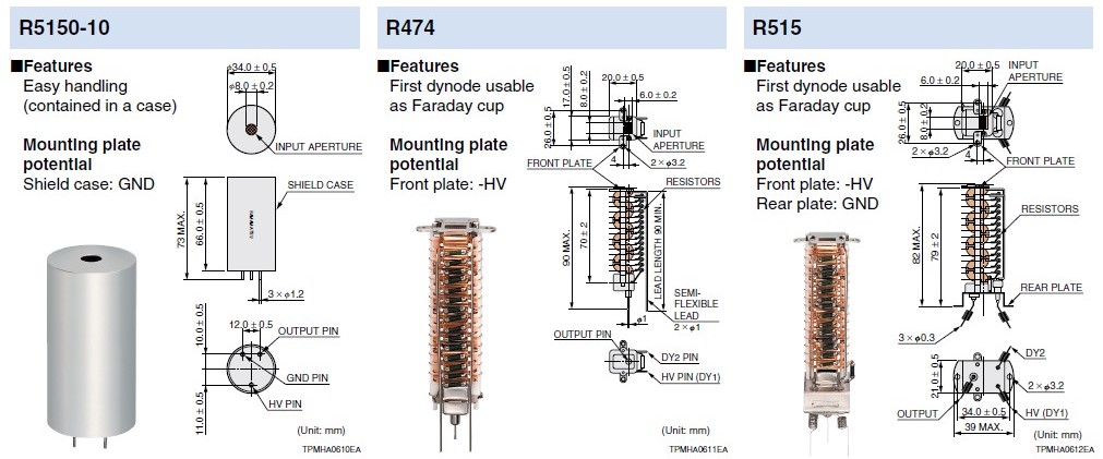
R5150-10 |
Box-and-line |
17 |
Cu-BeO |
φ8 |
|
R474 |
Box-and-grid |
16 |
Cu-BeO |
8 x 6 |
|
R515 |
Box-and-grid |
16 |
Cu-BeO |
8 x 6 |
|
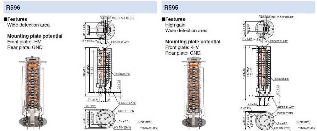
R596 |
Box-and-grid |
16 |
Cu-BeO |
12 x 10 |
|
R595 |
Box-and-grid |
20 |
Cu-BeO |
12 x 10 |
|
Type No. |
Supply voltage |
Gain |
Rise time |
Dark current |
Total resistance |
Detection ion polarity |
Anode to all other electrode capacitance |
|
R4146-10 |
-1800 |
1 x 10⁷ |
3.5 |
0.1 |
21 |
Positive |
4 |
|
R6985-80 |
-1900 |
1 x 10⁶ |
4.5 |
0.1 |
17.15 |
Positive/ |
1.8 |
|
R8811 |
-1500 |
1 x 10⁵ |
1.6 |
0.1 |
13 |
Positive |
0.8 |
|
R2362 |
-2700 |
1 x 10⁶ |
3.5 |
1 |
23 |
Positive |
23 |
|
R5150-10 |
-1800 |
1 x 10⁷ |
1.7 |
0.1 |
19.5 |
Positive |
4 |
|
R474 |
-1500 |
1 x 10⁶ |
11.8 |
0.1 |
16 |
Positive |
5 |
|
R515 |
-1500 |
1 x 10⁶ |
11.8 |
0.1 |
16 |
Positive |
4 |
|
R596 |
-1500 |
2 x 10⁶ |
12.6 |
0.1 |
16 |
Positive |
9 |
|
R595 |
-1500 |
4 x 10⁶ |
14.4 |
0.1 |
20 |
Positive |
9 |
|
Type No. |
Operating gain |
Anode to first dynode voltage |
Conversion voltage |
Faraday cup voltage |
Average anode current |
Bake-out temperature 1x10⁻⁴ Pa |
Operating vacuum level |
|
R4146-10 |
1 x 10⁸ |
2500 |
— |
— |
10 |
350 |
1 x 10⁻² |
|
R6985-80 |
1 x 10⁸ |
3000 |
±10 |
— |
10 |
— |
1 x 10⁻² |
|
R8811 |
5 x 10⁶ |
2000 |
— |
-200 |
10 |
350 |
1 x 10⁻² |
|
R2362 |
1 x 10⁸ |
4000 |
— |
— |
10 |
350 |
1 x 10⁻² |
|
R5150-10 |
1 x 10⁸ |
3500 |
— |
— |
10 |
350 |
1 x 10⁻² |
|
R474 |
1 x 10⁸ |
4000 |
— |
-100 |
10 |
350 |
1 x 10⁻² |
|
R515 |
1 x 10⁸ |
4000 |
— |
-100 |
10 |
350 |
1 x 10⁻² |
|
R596 |
1 x 10⁸ |
4000 |
— |
— |
10 |
350 |
1 x 10⁻² |
|
R595 |
1 x 10⁸ |
5000 |
— |
— |
10 |
350 |
1 x 10⁻² |
CONSTRUCTION AND OPERATING PRINCIPLE
An electron multiplier mainly consists of a input aperture, an electron multiplying section (dynode section), an anode, and voltage-divider resistors.
Electron multipliers operate in a vacuum and guide the particles or rays (positive/negative ions, vacuum UV rays, soft X-rays, etc.) so as to enter the first dynode. The first dynode is excited by such particles or rays and emits secondary electrons from its surface. These electrons are multiplied in cascade by the second and following dynodes and a cluster of secondary electrons finally reaches the anode and is output as a signal.
ELECTRON MULTIPLYING SECTION
Electron multipliers operate with a high S/N ratio since they have low noise and high gain. This low noise and high gain is achieved by an electron multiplying section made up of 13 to 23 stages of electrodes called dynodes. Before using an electron multiplier, it is first exposed to air once and then installed in equipment. The dynode therefore uses materials that exhibit stable characteristics and less deterioration even when exposed to air. Hamamatsu electron multipliers are designed and produced based on our advanced technology for photomultiplier tubes and so have high performance. The dynode structures in the electron multiplying section are described below.
1) Box-and-grid type
This type consists of a train of quarter cylindrical dynodes and offers good electron collection efficiency and excellent uniformity. This type is likely to resist voltage breakdown even
2) Circular-cage type
The circular-cage type features a com- pact design and fast time response.
3) Linear-focused type
The linear-focused type exhibits fast time response and has a thin configuration that is easy to design and use.
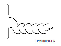
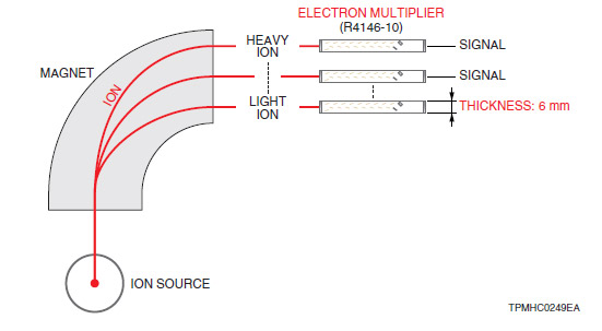
Because of these advantages the linear-focused type is frequently used in magnetic field deflection mass spectrometers where multiple detectors need to be installed side-by-side.
4) Box-and-line type
The structure of this type consists of a combination of box-and-grid and linear-focus dynodes. This type offers better time response than the box- and-grid type and higher ion collection efficiency than the linear-focused type.
5) Coarse mesh type
This type has a structure of wire dynodes with a triangle cross section stacked in the form of a mesh. This structure ensures excellent linearity and is less affected by magnetic fields. Compared to other dynode structures this type makes it easier to design a detector with a wider effective area.
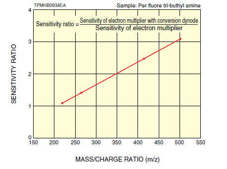
CONVERSION DYNODE (CD)
The acceleration of ions differs according to their mass. The speed at which ions enter the first dynode affects the secondary electron emission efficiency, so the higher the speed, the better the efficiency. When detecting ions with a large mass (for example, polymer compounds), the ions must be accelerated by a high potential to obtain a speed great enough to maintain a sufficient secondary electron emission efficiency. Conversion dynodes (CD) are usually used to give a high potential to such ions with a large mass.
SENSITIVITY
Electron multipliers can be used to detect and measure ions, vacuum UV rays, soft X-rays, and other rays by selecting a particular material for the first dynode
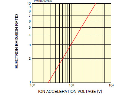
1) Ions
When one ion enters and strikes the first dynode, multiple electrons are emitted from the first dynode. The number of the emitted electrons depends on the mass of the ion and the acceleration voltage. The figure below shows how the electron emission ratio depends on the acceleration voltage when detecting nitrogen ions.
2) Light
Hamamatsu electron multipliers use beryllium copper oxide (Cu-BeO) or aluminum oxide (Al2O3) for the first dynode. Beryllium copper oxide is sensitive to soft X-rays to UV light at around 300 nm.
Depending on the wavelength incident on the first dynode or the usage, the first dynode can be replaced with a dynode on which an alkali-halide material is deposited. This gives the first dynode spectral response characteristics starting from just a few nanometers.
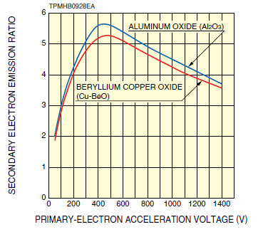
3) Electrons
The material used for the first dynode also has sensitivity to electrons having an energy level exhibited by Auger electrons, secondary electrons, and reflection electrons. The figure below shows the relation between the primary-electron acceleration voltage for beryllium copper oxide and aluminum oxide and the secondary electron emission ratio. The secondary electron emission ratio is at a maximum when the primary-electron acceleration voltage is about 400 V to 500 V
GAN
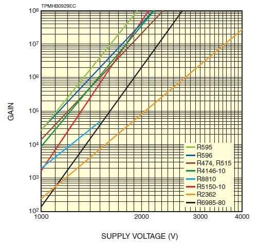
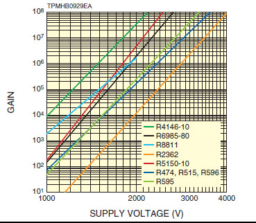
The gain of an electron multiplier is given by the following equation
 ) = A X Ebbkn A : constant
Ebb: supply voltage
k : value determined by electrode structure and material n : number of dynode stages
This equation reveals that the gain () is proportional to the supply voltage. The figure below shows how the gain of typical electron multipliers varies with the supply voltage.
The circuit system shown in the following block diagram can be used to measure the gain of an electron multiplier operat- ing under single ion input conditions. The pulse height ana- lyzer measures the total number of counts per second; and the ammeter measures the output current value under the same conditions. The gain is then calculated by "output cur- rent/elementary charge/number of counts per second."
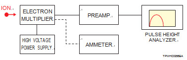
If an oscilloscope is used, the gain can be calculated by the "area of output pulse waveform (charge amount) divided by the elementary charge." When using an electron multiplier equipped with a Faraday cup, the gain can also be expressed as the ratio of the anode output current after multiplication by dynode to the input current to the Faraday cup.
DARK CURRENT AND NOISE
The beryllium copper oxide and aluminum oxide used for the secondary emissive surface of dynodes have a high work
1. Thermionic electrons are emitted from secondary electron emissive surface of dynode
2.Leakage current from dynode support materials
3.Field emission electron current of dynode
Hamamatsu electron multipliers have dark current of about 1 pA 1 when supply voltage providing a gain of 106.
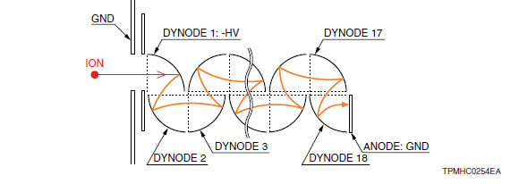
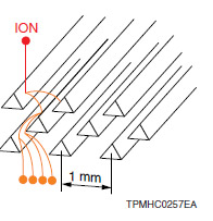
ON SOURCE NOISE
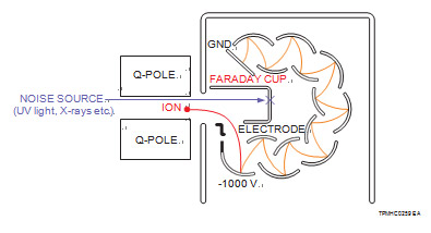
In some mass spectrometers, an ion source, analyzer, and ion detector are arrayed in a straight line. The ion source ionizes asample but at the same time generates UV light and X-rays. These UV light and X-rays will cause noise if they pass through the analyzer and enter the electron multiplier. This noise is refer- red to as "ion source noise". To reduce this noise component, the first dynode or conversion dynode is arranged at a position slight- ly offset from the ion input aperture and an electric field lens cre- ated by a special electrode is used to allow only the sample ions to enter the first dynode or conversion dynode. This is called an "off-axis structure". The figure below shows the ion detection mechanism of an off-axis electron multiplier.
VACUUM LEVEL AND NOISE
The vacuum level affects the generation of noise in an electron multiplier. The noise is usually low at a vacuum level for example of 10-5 Pa, but increases as the vacuum level drops for example to 0.1 Pa. We recommend operating the electron multiplier at a vacuum level higher than about 10-2 Pa although the level may depend on the operating gain and the type of detector.
DC LINEARITY
Electron multipliers are shipped with a voltage-divider circuit assembled inside. The current that will flow in the voltage-divider circuit can be calculated by the total resistance of the voltage- divider circuit divided by the supply voltage.The relation between the input ion energy and the average anode current maintains an ideal linearity in a certain energy range. However, as the inputenergy increases or the amount of input ions increases, the output current also increases and becomes saturated near the value of the current flowing in the voltage-divider circuit. To maintain the ideal linearity, we recommend regulating the average anode current to 1/20th or less of the current flowing in the voltage-divider circuit. To achieve a high counting efficiency, it is necessary to choose a linear-focused-dynode electron multiplier that has fast time response and a voltage-divider circuit with lower total resistance. However, please note that the voltage-divider circuit is likely to generate more heat as the resistance is lowered.
LIFE CHARACTERISTICS
The lifetime of electron multipliers is usually affected by the operating gain, output current and the operating vacuum level. The following three factors are the main limits on the lifetime.
1.Deterioration in the first dynode or conversion dynode by incident ions
2.Deterioration in the secondary electron emission capability of dynodes near the last stage, which is caused by collision of large amounts of electrons
3.Contamination adhering to the secondary emissive surface
We conducted in-house testing by operating our electron multipliers under conditions where residual gases (carbon) are present and analyzed the results. Larger amounts of carbon deposits were detected on the latter dynode stages where the electron density was high, so we think that the contamination (residual gases, etc.) inside the analyzer (especially the vacuum chamber) has a significant effect on the lifetime.
Also, unlike photomultiplier tubes, electron multipliers are not completely sealed and so may possibly be exposed to surrounding gases, moisture, oil or grease and other items during storage, causing deterioration in the characteristics.
CONNECTION METHODS
The inter-electrode voltage is supplied through a voltage-divider circuit made up of resistors connected in series.
The connection methods are described below according to the polarity of the ions to detect.
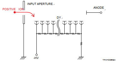
1.Positive ion detection
As shown in the figure below, the input aperture and the last dynode are grounded and a negative high voltage is supplied to the first dynode during operation.
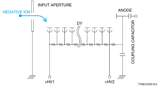
2.Negative ion detection
As the following figure shows, the input opening is grounded, a positive high voltage (+HV1) is supplied to the first dynode to draw negative ions, and another positive high voltage (+HV2) to the last dynode. The difference in voltage between +HV1 and +HV2 creates a difference in potential. The last dynode is connected to the anode via resistor, and a coupling capacitor is connected to the anode to prevent the positive high voltage from being input to the externally connected measuring device. This means that DC signals cannot be extracted by this measurement method.
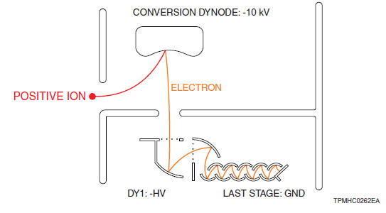
3.Positive ion detection using electron multiplier with conversion dynode
When measuring positive ions, a negative high voltage (about -10 kV) is supplied to the conversion dynode, another negative high voltage is applied to the first dynode, and the last dynode is grounded. Positive ions are converted into electrons by the conversion dynode.
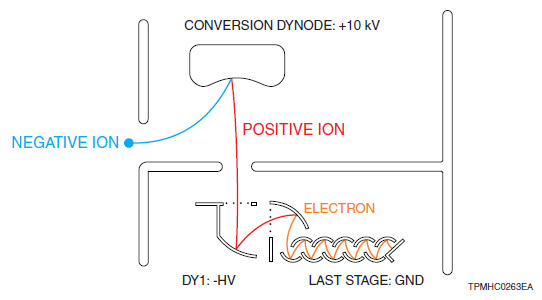
4.Negative ion detection using electron multiplier with conver- sion dynode
When measuring negative ions, a positive high voltage (about +10 kV) is supplied to the conversion dynode, a negative high voltage is applied to the first dynode, and the last dynode is grounded. Negative ions are converted into positive ions by the conversion dynode and the positive ions are then converted into electrons by the first dynode.
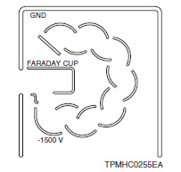
5.Faraday cup
Hamamatsu also provides electron multipliers equipped with a Faraday cup function. The Faraday cup function and electron multiplying function cannot be used simultaneously. If a high voltage is supplied to the electron multiplying section while operating the Faraday cup, the incoming ions shift their trajectories toward the electron multiplying section and so fail to reach the Faraday cup.
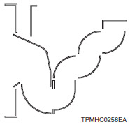
6.Dual-mode electron multiplier
Dual mode allows both the analog output and pulse output to be measured with just one detector. As the figure below shows, the analog output is measured at an intermediate stage of the electron multiplying section while the pulse output is measured at the last stage.
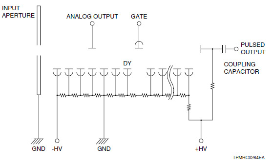
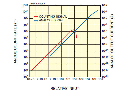
When the amount of ions is very small, a pulse output function which provides high gain is used to count the output pulses. When the amount of ions is large, the analog output with low gain is used to make measurement. This prevents the detector from being saturated and allows measurements ranging from a small to a large quantity of ions. As seen from the figure below, a wide dynamic range of 9 orders of magnitude can be obtained.
檔案下載