- HOME
- 產品介紹
- 半導體事業部
- Hamamatsu Photonics
- Optical components
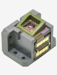
- 2D Laser Scanning MEMs mirror: S13989-01H
2D Laser Scanning MEMs mirror: S13989-01H
![]() +886-2-8772-8910
+886-2-8772-8910
|
Parameter |
Symbol |
Condition |
Min. |
Typ. |
Max. |
Unit |
|
|---|---|---|---|---|---|---|---|
|
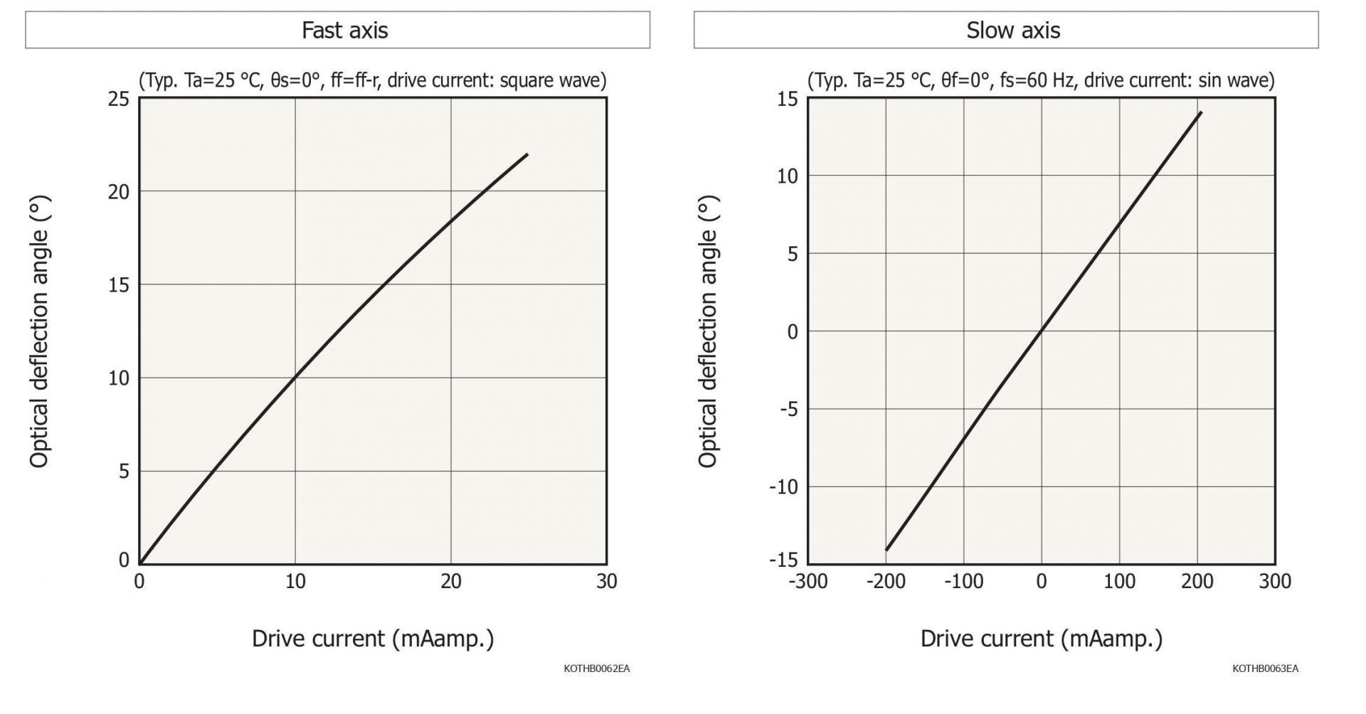
Fast axis |
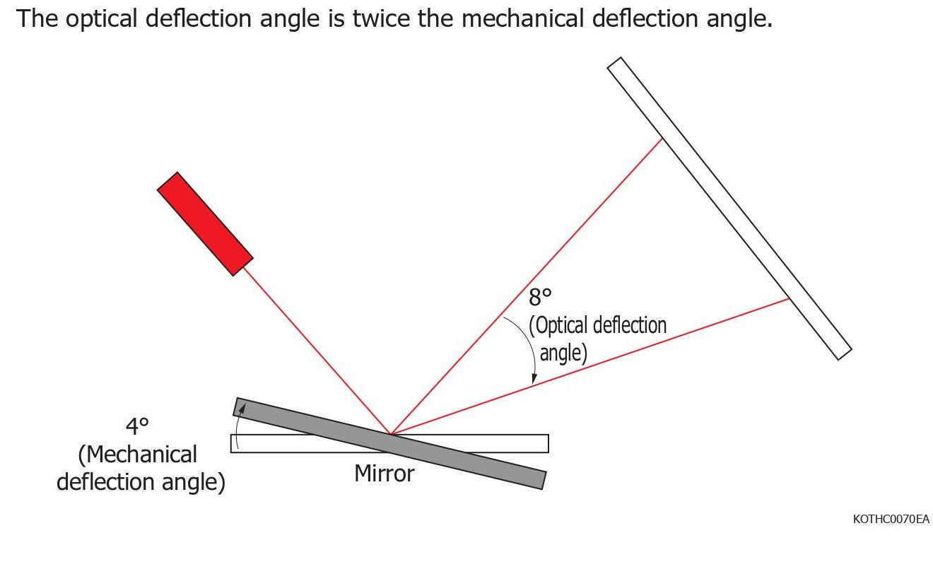
Optical deflection angle*1 |
θf_max |
|
-22 |
- |
22 |
° |
|
Slow axis |
Drive current*2 |
Is_dc |
DC current |
-100 |
- |
100 |
mAdc |
|
Optical deflection angle*1 |
θs_max |
|
-14 |
- |
14 |
° |
|
|
Power consumption*3 |
Pcoil |
|
- |
- |
520 |
mW |
|
|
Operating temperature*4 |
Topr |
No dew condensation*5 |
-20 |
- |
60 |
°C |
|
|
Storage temperature |
Tstg |
No dew condensation*5 |
-40 |
- |
85 |
°C |
|
|
Parameter |
Min. |
Typ. |
Max. |
Unit |
|
|
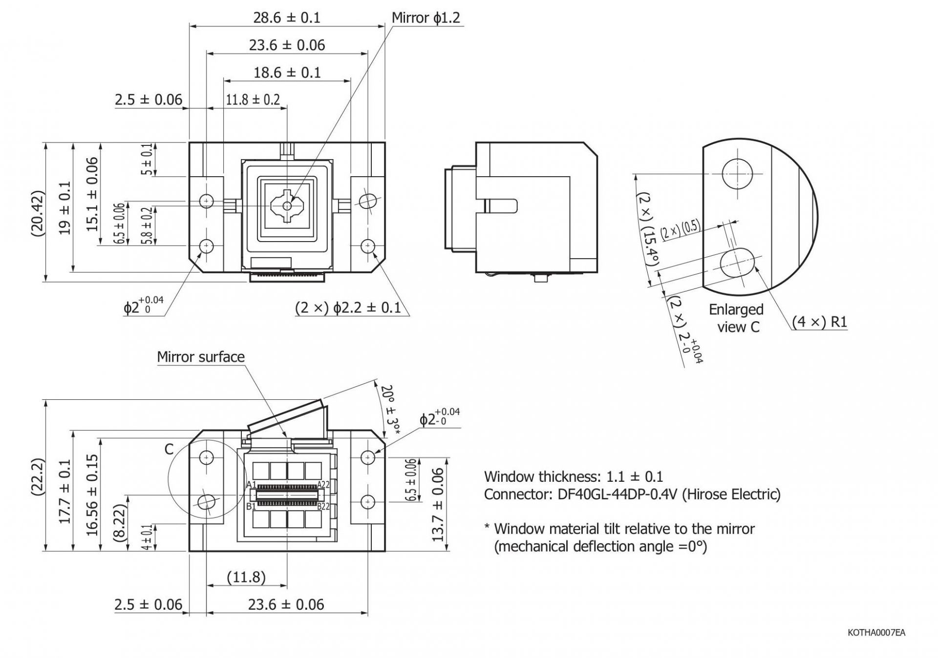
Mirror size |
ϕ1.21 |
ϕ1.23 |
ϕ1.25 |
mm |
|
|
Mirror material |
Aluminum alloy |
- |
|||
|
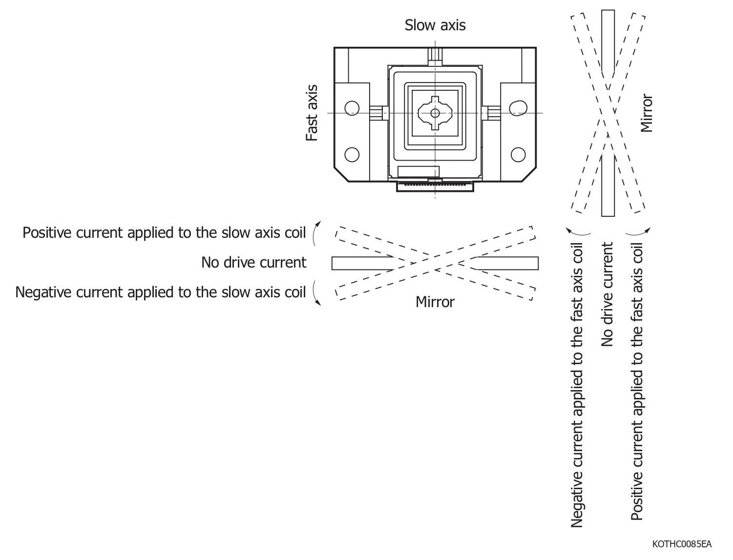
Operation mode |
Fast axis |
Non-linear mode (resonant mode) |
- |
||
|
Slow axis |
Linear mode |
- |
|||
|
Parameter |
Symbol |
Condition |
Min. |
Typ. |
Max. |
Unit |
|
|---|---|---|---|---|---|---|---|
|
Fast axis |
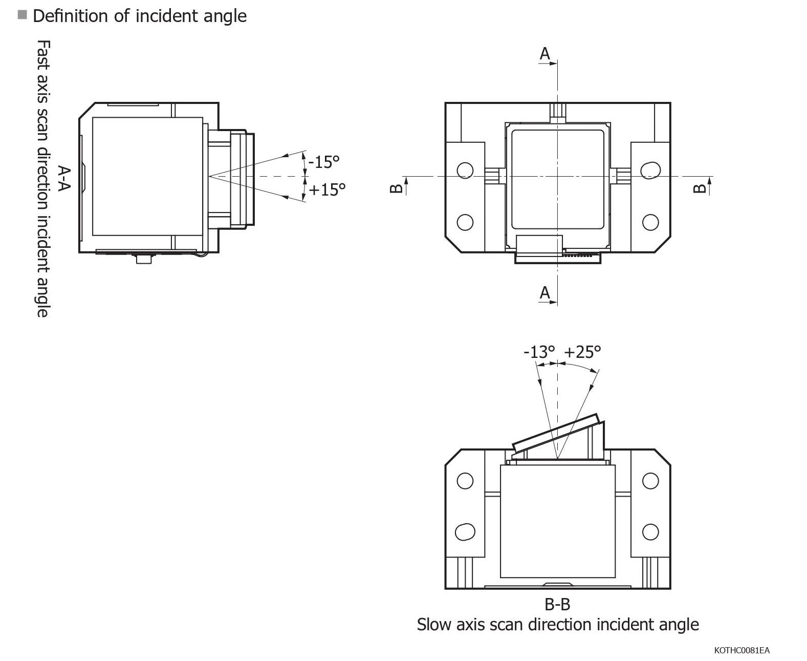
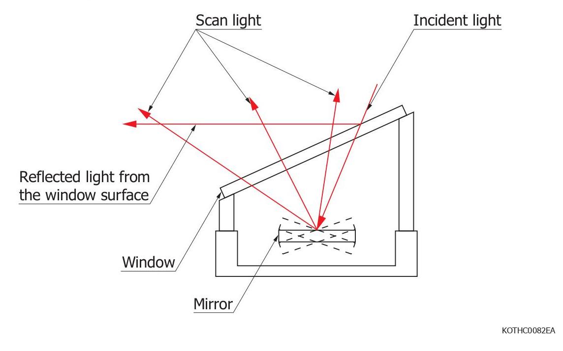
Incident angle*6 |
ϕf |
|
-15 |
0 |
15 |
° |
|
Optical deflection angle*7 |
θf |
|
-20 |
- |
20 |
° |
|
|
Drive frequency |
ff |
|
Resonant frequency*8 |
Hz |
|||
|
Slow axis |
Incident angle*6 |
ϕs |
|
-13 |
20 |
25 |
° |
|
Optical deflection angle*7 |
θs |
|
-12 |
- |
12 |
° |
|
|
Drive frequency |
fs |
|
10 |
- |
100 |
Hz |
|
|
Operating temperature*9 |
Topr |
No dew condensation*10 |
-20 |
25 |
60 |
°C |
|
|
Parameter |
Symbol |
Condition |
Min. |
Typ. |
Max. |
Unit |
||
|---|---|---|---|---|---|---|---|---|
|
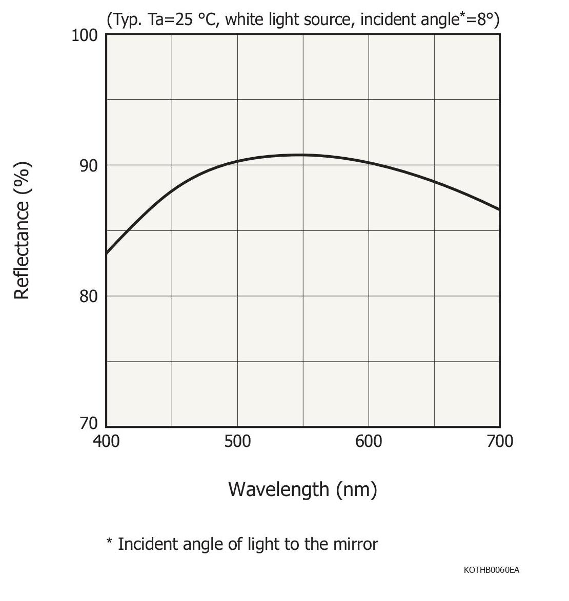
Reflectance*11 |
R |
λ=460 to 640 nm |
80 |
- |
- |
% |
||
|
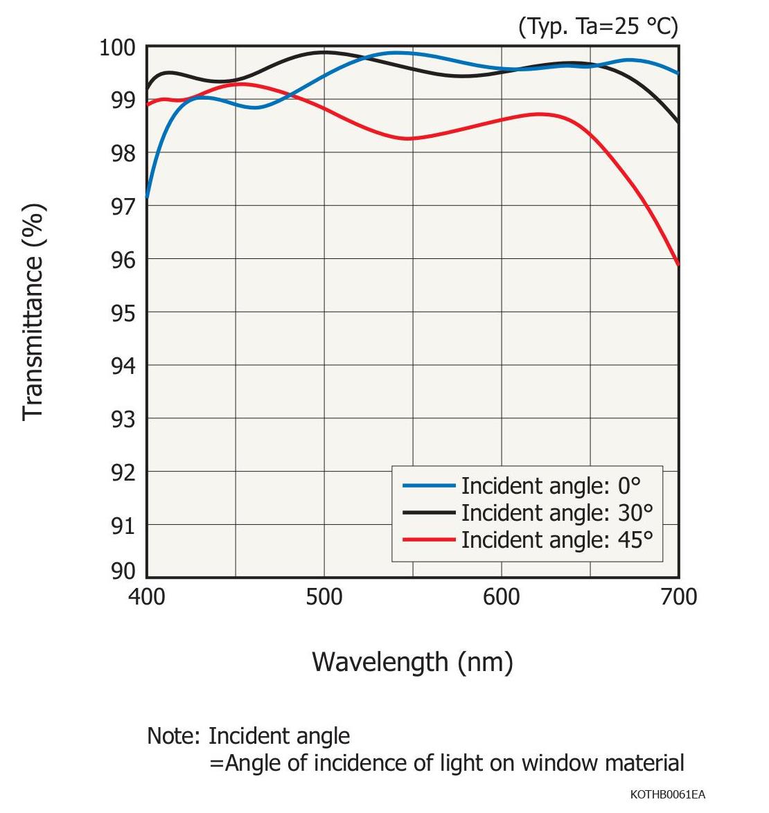
Transmittance of window material*12 |
T |
θin=0 to 43°*13, λ=460 to 640 nm |
95 |
- |
- |
% |
||
|
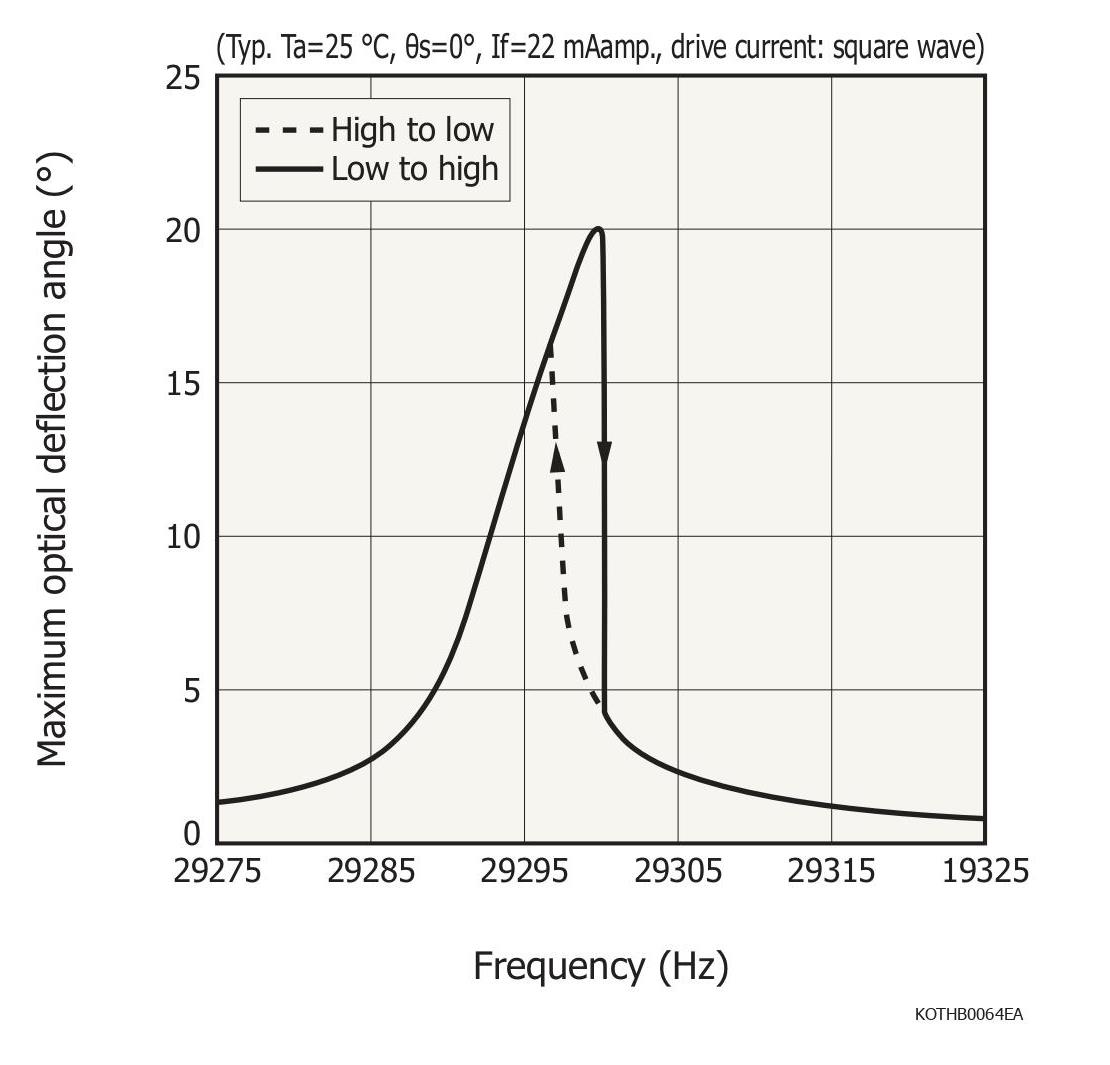
Fast axis |
Resonant frequency |
ff-r |
Ta=25 °C, θf=±20°, Is=0 mA, square wave |
28.6 |
29.3 |
30 |
kHz |
|
|
Drive current |
If |
Ta=25 °C, ff=ff-r, θf=±20°, Is=0 mA, square wave |
12 |
22 |
34 |
mAamp. |
||
|
Coil resistance |
Rf |
Ta=25 °C, If=0.1 mA, Is=0 mA |
7.5 |
10.5 |
13.5 |
Ω |
||
|
Back electromotive force |
Vf |
Ta=25 °C, θf=±20°, Is=0 mA |
23 |
28 |
33 |
mVamp. |
||
|
Vs |
Ta=25 °C, θf=±20°, Is=0 mA |
16 |
20 |
24 |
mVamp. |
|||
|
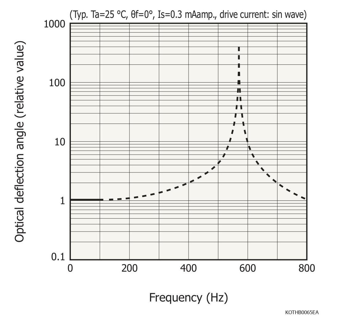
Slow axis |
Resonant frequency |
fs-r |
Ta=25 °C, Is=0.3 mAamp. (sin wave) If=0 mA |
525 |
575 |
625 |
Hz |
|
|
Quality factor |
Qs |
Ta=25 °C, Is=0.3 mAamp. (sin wave) If=0 mA |
320 |
400 |
480 |
- |
||
|
|
|
Ta=25 °C |
θs=+12° |
140 |
175 |
210 |
mAamp. |
|
|
Drive current |
Is |
θs=-12° |
-210 |
-175 |
-140 |
mAamp. |
||
|
Coil resistance |
Rs |
Ta=25 °C, If=0 mA, Is=0.1 mA |
6 |
8 |
10 |
Ω |
||
|
Temperature sensor |
Resistance |
Rth |
Ta=25 °C, Ith=0.1 mA, If=0 mA, Is=0 mA |
230 |
300 |
370 |
Ω |
|
|
Resistance temperature coefficient |
α |
|
0.36 |
0.38 |
0.4 |
%/°C |
||
檔案下載